![]()
Creating a positioned sketch enables you to define (and later change) explicitly the position of the sketch absolute axis. This offers the following advantages:
- You can use the absolute axis directions like external references for the sketched profile geometry.
- When the geometry of the part evolves and the associated position of the sketch changes, the shape of the sketched profile (2D geometry of the sketch) remains unchanged (even if the sketched profile is under-constrained).
Creating a positioned sketch also ensures associativity with the 3D geometry.
You will position the sketch absolute axis as follows:
- its origin will be on the axis of revolution,
- its horizontal (H) direction will be parallel to the flat face,
- its vertical (V) direction will be normal to the flat face.
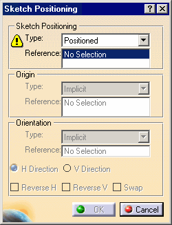
In the Type field in the Sketch Positioning area, two options are available:
-
Positioned (pre-selected): creates a positioned sketch for which you specify the origin and orientation of the absolute axis.
-
Sliding: creates a "non-positioned" sketch, i.e. a sketch for which you do not specify the origin and orientation of the absolute axis. This option is mainly used for compatibility with non-positioned sketches, and to enable you to turn them into positioned sketches. With the Sliding option, the sketch absolute axis may "slide" on the reference plane when the part is updated.
-
Keep the Positioned option selected.
You will now specify the reference plane for the sketch. -
Make sure the Reference field is active, and select the blue surface (Shaft.1).
The Sketch Positioning dialog box is updated: the Reference field now indicates the reference plane. Also, the Type fields of the Origin and Orientation areas are activated and the Implicit mode is pre-selected.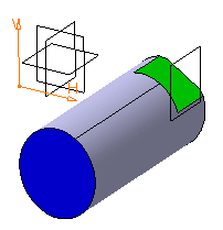
With the Implicit mode, the sketch origin point and the sketch orientation are positioned according to the geometry used for the sketch plane:
-
When the sketch support is a plane, the sketch origin point is a projection of the part origin point in the sketch plane, and the sketch orientation is parallel to the reference plane directions.
-
When the sketch support is defined by two secant lines, the origin is at the intersection of these. The H direction is co-linear to the first line, and its orientation directly depends on the orientation of this line. The V direction is deduced from the second line, which is not necessarily orthogonal to the first line. This second line simply defines, depending on its orientation, the side where the V direction will be positioned in relation to the H direction.
You will now specify the absolute axis origin so to make it coincident with the axis of revolution of the part.
-
Select Curve intersection in the Type field of the Origin frame.
The Reference field is activated.
The options available for defining an origin are:
- Implicit
- Part origin
- Projection point
- Intersection between 2 lines
- Curve intersection
- Middle point
- Barycenter
-
Select the cylindrical surface to make its axis intersect with the absolute axis origin.
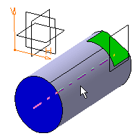
The absolute axis of the sketch is now positioned on this axis. Its orientation has not changed.
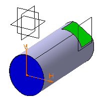
-
You will now specify the absolute axis orientation according to an edge of the flat face. The options available for defining an orientation are:
Select Parallel to line in the Type field of the Orientation frame.
The Reference field is activated.
-
Select an edge of the flat face.
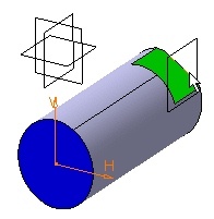
The absolute axis of the sketch is now oriented like the selected edge.
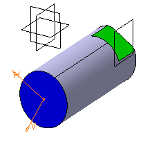
You will now invert the H direction and make the V direction normal to the flat face. To do this, start by selecting V Direction in the Orientation area to specify that you want the orientation to be defined according to the V direction.
-
Select Reverse V to revert the V direction and select the Swap check box to swap H and V directions.
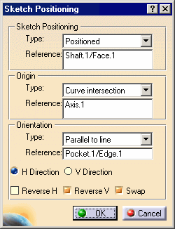
The sketch is now positioned as wanted. 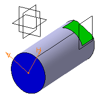
-
Click OK to validate and exit the Sketch Positioning dialog box.
You are now in the Sketcher workbench and ready to sketch a profile for the retaining bracket.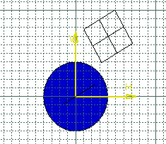
-
The absolute axis (its origin point, both its directions and the grid) can be used to specify the position and dimensions of the 2D geometry because it is associative with the part.
-
With positioned sketches, the origin and directions of the absolute axis are similar to external references (Use-Edges) obtained using additional projections or intersections when creating non-positioned sketches.
-
In this exercise, you did not create any constraints on 2D geometry: the geometry is under-constrained. Yet, if you move or resize the part (no matter how significantly), the profile you sketched will remain absolutely unchanged. Its shape will not be altered: thanks to the fact that the position of its absolute axis is explicitly defined, it is automatically pre-positioned in 3D before its 2D resolution.
-
At any time after creating a positioned sketch, you can change the reference plane, the origin and the orientation of the absolute axis by specifying the new geometry in the associated Reference field. To do this from the 3D, right-click the positioned sketch in the specification tree, point to [sketch name] object in the contextual menu, and then select Change sketch support.
