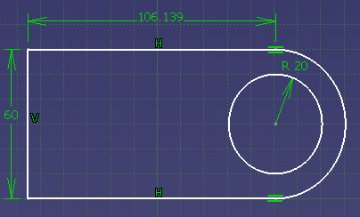
Using the Parents/Children Command
-
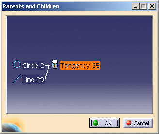
Right-click the tangency constraint from the specification tree and select Parents/Children.
The Parents and Children dialog box is displayed. The elements to which the selected constraint is related are shown within the dialog box.
If you wish to see more details on the parents (here the circles), just double-click one of the element in the dialog box.
-
Click OK in the dialog box.
Using the Sketch Solving Status
-
Select Circle.2.
-
Click Constraints Defined in Dialog Box
 in the Constraints toolbar.
The Constraint Definition dialog box is displayed.
-
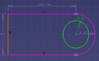
Select the Radius / Diameter option.
The geometry color has turned to purple meaning that it is over-constrained.
-
Click OK in the dialog box.
-
Click Sketch Solving Status
 from the 2D Analysis Tools in the Tools toolbar.
This command gives you a quick diagnosis of the geometry status.
The Sketch Solving Status dialog box is displayed and informs you of the general sketch status, whether it is under, over or iso-constrained. Meanwhile, the information given in the Sketch Solving Status dialog box is highlighted in red in the geometry area and the element that are here under-constrained are highlighted.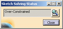
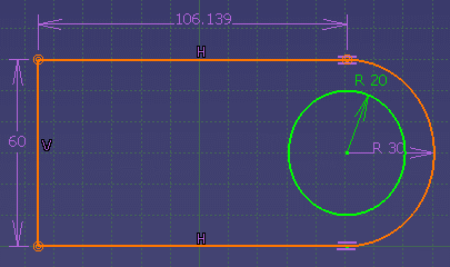
Using the Sketch Analysis
-
The Sketch Solving Status dialog box is still displayed. Click Sketch Analysis
 available in the Sketch Solving Status dialog box.
The Sketch Analysis dialog box is displayed and information is given on every element of the sketch as long as the created constraints in the diagnostic tab.
Construction elements appear with a blue color in the geometry.
Note that you have the possibility to sort the elements displayed in the dialog box by Name, status or Type, by clicking the appropriate tab. Note that you can select elements from the dialog box and they will be highlighted in the geometry area.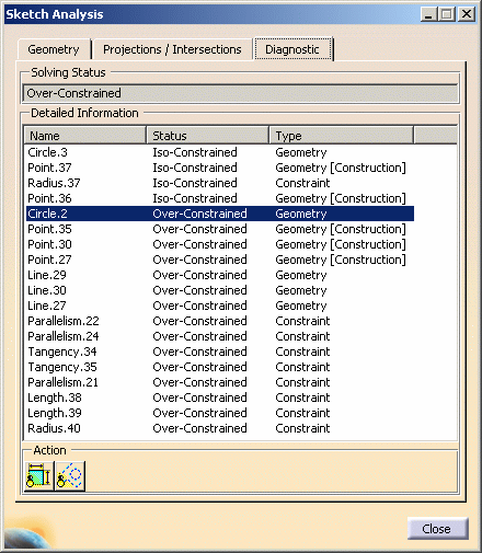
Note that you can now identify the construction elements and, for instance, swap them into standard elements.
-
Select Hide Construction Geometries
 from the Sketch
Analysis dialog box.
All the construction elements are hidden both from the dialog box and the geometry area. These elements are grayed in the specification tree.
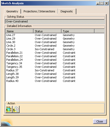
-
Now select Hide Constraints
 .
.
All the constraints are hidden both from the geometry and the dialog box. These elements are grayed in the specification tree.
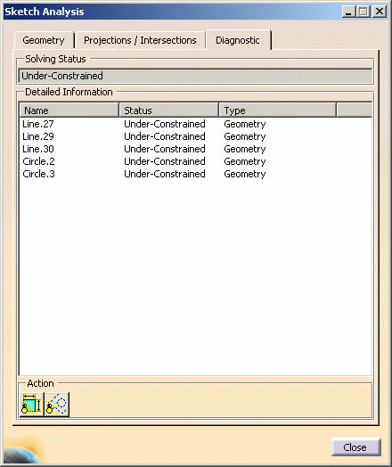
For more details on the Sketch analysis command, see Analyzing Sketched Geometry.