The Sketch tools toolbar is displayed at the bottom
right part of the application.

It provides the following options commands:
|
|
Working with the Grid Option | |
|
|
Working with the Snap to Point Option | |
|
|
Creating Construction/Standard Elements | |
|
|
Creating Geometrical Constraints | |
|
|
Creating Dimensional Constraints | |
|
|
Value Fields | |
You do not necessarily visualize the whole Sketch tools toolbar. Just undock it to display all the available options and fields.
Working with the Grid Option
The Grid option is directly available from the Sketch
tools toolbar. Clicking Grid
![]() displays the grid in your session.
displays the grid in your session.
The grid spacing and graduations are defined using the Tools > Options > Mechanical Design > Sketcher command. For more information, refer to Customizing.
Working with the Snap to Point Option
If activated, Snap to Point
![]() makes your sketch begin or end on the points of the grid. As you are
sketching the points are snapped to the intersection points of the
grid. Note that this option is also available in the Tools > Options,
Mechanical Design > Sketcher option at the left of the dialog box (Sketcher
tab). For more information, see
Infrastructure
user's guide (Customization Settings).
makes your sketch begin or end on the points of the grid. As you are
sketching the points are snapped to the intersection points of the
grid. Note that this option is also available in the Tools > Options,
Mechanical Design > Sketcher option at the left of the dialog box (Sketcher
tab). For more information, see
Infrastructure
user's guide (Customization Settings).
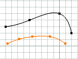
In the following example:
- the black spline was created with Snap to Point on. The points are on the grid.
- Conversely, the highlighted spline was created with the Snap to
Point option deactivated.

When SmartPick is active, points may not snap at the intersection points of the grid. Care that they will necessarily snap on an horizontal or a vertical grid subdivision.
Creating Construction/Standard Elements
You can create two types of elements: standard elements and construction elements. Note that creating standard or construction elements is based upon the same methodology.
If standard elements represent the most commonly created elements, on some occasions, you will have to create a geometry just to facilitate your design. Construction elements aim at helping you in sketching the required profile.
-
Click Construction/Standard Element
 in the Sketch tools toolbar so that the elements you are now
going to create be either standard or construction element.
As construction elements are not taken into account when creating features, note that they do not appear outside the Sketcher.
- When they are not used anymore, construction elements are automatically removed.
- Note that in the case of hexagons, construction element type is automatically used for secondary circles. This type of sketch is interesting in that it simplifies the creation and the ways in which it is constrained. Setting a radius constraint on the second circle is enough to constrain the whole hexagon. Just imagine what you would have to do to constrain hexagons sketched with no construction circles!
Creating Geometrical Constraints
When selected, Geometrical Constraint
![]() allows you to force a limitation between one or more geometry elements.
allows you to force a limitation between one or more geometry elements.
Creating Dimensional Constraints
When selected, Dimensional Constraint
![]() allows you to force a dimensional limitation on one or more profile type
elements provided you use the value fields in the Sketch tools
toolbar for creating this profile.
allows you to force a dimensional limitation on one or more profile type
elements provided you use the value fields in the Sketch tools
toolbar for creating this profile.
To know more about sketcher constraints, refer to Setting Constraints, and Infrastructure user's guide (Customization Settings).

Value Fields

The values of the elements you sketch appear in the Sketch tools toolbar as you move the cursor. In other words, as you are moving the cursor, the Horizontal (H), Vertical (V), Length (L) and Angle (A) fields display the coordinates corresponding to the cursor position.
- You can select the desired field of the Sketch tools
toolbar and type in the desired values:
- Using the mouse cursor.
- Using the Tab key.
- You can increment or decrement the value in a field using the Up key or Down key according to the grid options.
- When you select another field, the value in the previously selected filed is locked.
- Type any number fill by default the first field.
- Press Enter to validate your values.
You can also use these fields for entering the values of your choice. In the following scenario, you are going to sketch a line by entering values in the appropriate fields.
-
Click Line
 .
.
The Sketch tools toolbar displays information in the four value fields.
-
Enter the coordinates of the First Point.
-
Enter the coordinates of the Second Point.
or
-
Enter the length (L) of the line.
-
Enter the value of the angle (A) between the line to be created and the horizontal axis.
-
Click the first point on the line.
The line is created.
Depending on the number of fields available and the way you customize your toolbars, some fields may be truncated. What you need to do is just undock the Sketch tools toolbar.