This view plane definition will be used, via the View Plane dialog box for acknowledging the 3D relationship between views. This will be the case when creating a multiple view projection or when creating views using folding lines.
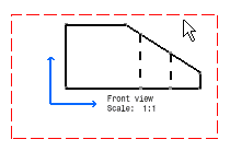
Define the front view plane
Activate the view in which you want to change the plane definition, by double-clicking on this view.
-
Click the View Plane Definition icon from the Multi View toolbar (not displayed by default).
OR

-
Select the Tools > Multi View > View Plane Definition command from the menu bar.
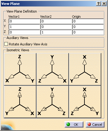
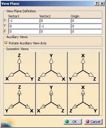
The View Plane dialog box appears with options on the view plane definitions for front views, auxiliary views and isometric views.
-
Select the desired options from the View Plane Definition area. In this case, enter 1 as the X value and 0 as the Y and Z values for Vector1; enter 1 as the Y value and 0 as the X and Z values for Vector2.
-
Click OK. The front view plane definition is updated.
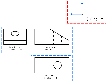
Define the auxiliary view plane:
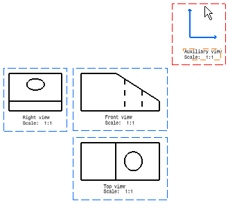
For creating an auxiliary view, you need to create any view first and then modify the view plane you want. In this case, we created an auxiliary view.
Make sure the view in which you want to change the plane definition is active. If it is not, double-click to activate it.
-
Click the View Plane Definition icon from the Multi View toolbar (not displayed by default).
OR
-
Select the Tools > Multi View > View Plane Definition command from the menu bar.
The View Plane dialog box appears.

-
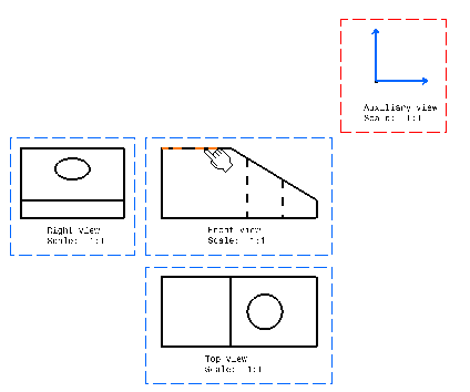
In another orthogonal view, click the line that you want to use to define the auxiliary view plane.
-
Select the Rotate Auxiliary View Axis option to rotate the auxiliary view axis.
-
Click OK.
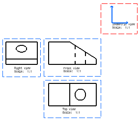
The axis automatically rotates in accordance with the dialog box values applied to the selected plane.
Define the isometric view plane:
Click the New View icon ![]() in order to create an empty view. In this case, position the cursor so as
to create an isometric view.
in order to create an empty view. In this case, position the cursor so as
to create an isometric view.
Activate the newly created view, in which you want to change the plane definition, by double-clicking it.
-
Click the View Plane Definition icon from the Multi View toolbar (not displayed by default).
OR
-
Select the Tools > Multi View > View Plane Definition command from the menu bar.
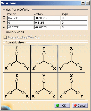
The View Plane dialog box appears. -
Enter the desired values in the dialog box (Isometric).
OR -
Select the desired pre-defined isometric view vectors. In this case, select YZX (center of the top row in the Isometric Views area).
-
Click OK. The isometric view plane definition is updated.
![]()