- create an isometric view.
- change the view properties to switch it to Raster mode, displaying shading with edges. Indeed, by default (i.e. as specified in Tools > Options > Mechanical Design > Drafting > View tab), all views are created as exact views.
Creating an Isometric View
-
Click the Isometric View
 in the Views toolbar (Projections sub-toolbar).
 -
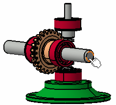
Now, in the assembly window, click on the desired plane on the 3D assembly to define the reference plane.
-
A green frame with the preview of the isometric view to be created, as well as blue manipulators, appear. These manipulators let you redefine the reference plane orientation of the view. For more information, refer to Before you begin in the User Tasks chapter.
-
Click to generate the view. A progress bar appears while the view is being created.
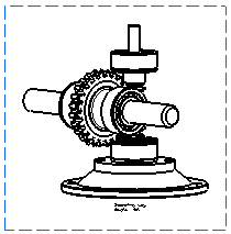
-
Optionally drag the view to position it as wanted on the drawing.
Changing the View Properties
-
Right-click the isometric view and select Properties.
-
On the View tab, check 3D Colors in the Dress-up area.
-
In the Generation Mode area, select Raster from the View generation mode drop-down list.
-
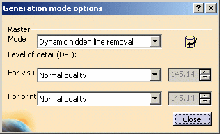
Click the Options button. The Generation Mode Options dialog box is displayed.
-
Select Shading with edges from the Mode drop-down list.
-
Click Close to exit the dialog box.
-
Back in the Properties dialog box, click OK to validate. A progress bar appears while your modifications are being taken into account. The view is now in Raster mode, displaying shading with edges.
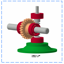
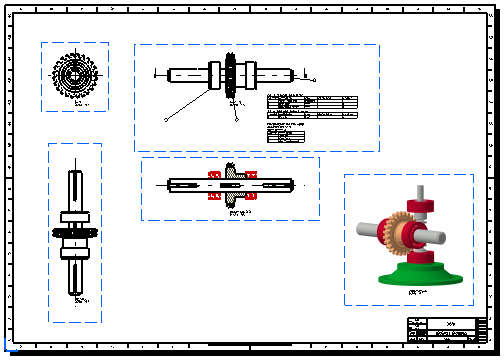
The resulting sheet now appears similar to what is shown here. Note that in this case, we re-positioned the views for better results.
-
You can now print this sheet. To do so, select File > Print. Make sure the print format you set when defining the sheet is the same as the print format of the printer.