A breakout view is one not in direct projection from the view containing the cutting profile. In other words, it is not positioned in agreement with the standard arrangement of views. A breakout view is often a partial section.
-
In the Drawing window, click Breakout View
 in the Views
toolbar (Break View sub-toolbar).
 -
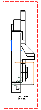
Click the first point of the breakout profile.
-
Click as many points as desired for creating the profile.
-
If needed, double-click to end the profile creation and close this profile automatically.
OR
Click on the profile first point to close and end the profile creation.

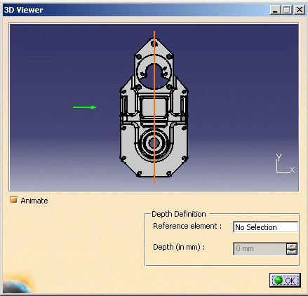
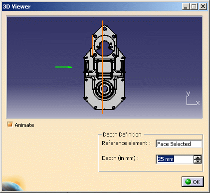
The 3D Viewer window appears, displaying the 3D part corresponding to the generated view. A green arrow indicates in which direction the breakout will be created. This window lets you position the 3D part according to a view you go over (on the drawing), provided the Animate option is checked.
This window also lets you visualize a view plane and use it to define the depth of the breakout. You can move this plane using one of these methods:
- directly in the 3D Viewer window, drag the plane to the desired location. This method does not let you define the depth of the breakout precisely. The breakout will not be associative with any element.
- in the drawing, place the cursor over an axis, a center line or an edge (circular or linear) of a perpendicular view. The plane will be moved accordingly. This method lets you break the view through a hole or a face, for example. The breakout will be associative with the selected element.
- in the drawing, select the edge which corresponds to the face that you will use as a reference element to define the depth of the breakout, and enter the depth in the appropriate 3D Viewer field. This method lets you define the depth of the breakout precisely. The breakout will be associative with the selected reference element and with the depth value.
-
Check the Animate option to visualize the 3D part in accordance with the position of the cursor on a generated view.
-
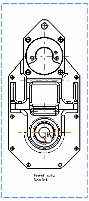
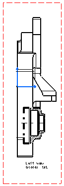
In the CATDrawing document, place the cursor over the front view (which is perpendicular to the left view).
-
In the CATDrawing document, place the cursor over the center line that will be used as an extremity plane, as shown below.
OR
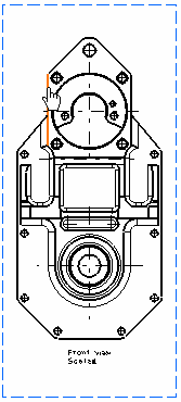
In the 3D Viewer window, click the Reference element field to select it. Then, in the CATDrawing document, select the edge which corresponds to the face that will be used as a reference element, and enter the breakout depth in the Depth (in mm) field (you can also define the depth by moving the red plane with the mouse).
-
Click OK in the 3D Viewer window. The breakout view is created.
More on Breakout Views
- Once created, the breakout view profile cannot be modified.
- You cannot apply a breakout and a break to the same view.
- section cuts,
- detail/ clipping views,
- broken views.
Removing a breakout
To remove a breakout, choose either of the following methods:
- Once the breakout view is created, right-click the view, and select
the Remove Breakout option.
All the breakouts will be removed. - Or right-click on the edge of a resulting breakout and select Generated item object, then Remove breakout. Only this breakout will be removed.
Propagating a breakout specification manually
Right-click the view, select the Apply Breakout To option and click another view you want to apply the breakout to.
Propagating a breakout specification automatically
Propagating a specification means generating a view (B) from another view (A) on which you previously performed an operation and including this operation in the generated view (B).
To generate views (projection, auxiliary, section, section cut and detail) from a breakout view, go to Tools > Options > Mechanical Design > Drafting from the menu bar, click on the Layout tab, and activate the Propagation of broken and breakout specification option.
For example, (i) you create a breakout view (view A) and activate the Propagation of broken and breakout specification option, you then (ii) generate a projection view (view B). As a result, the projected view (view B) will display this breakout area.
About line types
You can choose the line type you want to assign to the breakout view. To do this, go to Tools > Options > Mechanical Design > Drafting > View tab, click the Configure button next to View Linetype and select the desired option from the dialog box.
| If you choose the zigzag linetype (linetype #8), note that this linetype is just a graphical dress-up of the view. This means that if one line is relimited on the breakout line, then it will be relimited on the theoretical line as shown here, and not on the visualized zigzag line. | 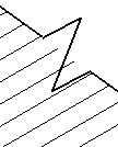 |
About patterns
The patterns which are used to represent the breakout are defined in the standards. For more information, refer to Pattern Definition in the Interactive Drafting User's Guide.
About patterns in breakouts from isometric views
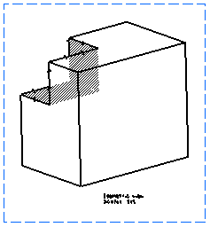
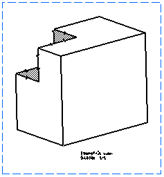
In versions prior to V5 R13, when creating breakouts on isometric views, in the case of overlapping faces, the pattern area used to go over the projected faces and edges. From R13 onwards, the pattern area is now limited to the face sectioned on the part, as shown below.
Previous behavior
New behavior
About the Cut in section views capability
In an assembly, you can define that given parts will or will not be sectioned when generated into section views or breakout views.
In the Assembly Design workbench, select one part, then the Edit > Properties command from the menu bar from and either activate or de-activate the Cut in section views option. You can also do this when overloading element properties in a view generated from a CATProduct.
About breakout views generated using the Approximate generation mode
You can now generate breakout views using the Approximate generation mode. For more information on the approximate generation mode, refer to Customizing Settings: View.
When generating breakout views using the Approximate generation mode, or when switching a breakout view from exact mode to approximate mode (i.e. via Edit > Properties), be aware of the following information:
Breakout direction
The breakout propagation direction must be perpendicular to the view plane. In other words, the breakout profile must be parallel to view plane.
Patterns
In the case of parts which use a material to which a specific pattern is associated, breakout views in Approximate mode do not inherit the material properties from the 3D, and therefore do not use the pattern associated to this material.
Pattern properties are not persistent: for instance, after switching an exact view to the approximate mode, and vice versa, the pattern may change.
The Cut in section views capability
If you choose to not cut elements in section views or breakout views (i.e. if you uncheck the Cut in section views option): note that this capability does not work for breakout views generated using the Approximate generation mode: selected elements will be cut. Likewise, if you switch an exact view to the approximate mode, the elements for which you unselected the Cut in section views option will be cut in the view.
![]()