-
Right-click the section view A-A.
-
Select Section view A-A object > Overload properties.
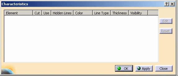
The Characteristics dialog box is displayed.
-
Select the element (part instance) that you want to edit. This element is highlighted in the drawing and listed in the dialog box.
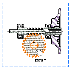

- You can also select several elements, if you want to overload their properties in the same way.
- In the case of several elements generated from a single part instance, all these elements are highlighted when you select one.
- You can select the elements in the 3D document, either by selecting a node in the specification tree or by multi-selecting the elements in the specification tree.
-
Select the element you want to edit (as there is just one in our example, it is already pre-selected) in the dialog box and click the Edit button.
The Editor dialog box is displayed.
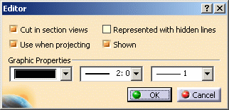
You can modify the following parameters:
-
Cut in section views: specifies that the 3D element will be cut in the section view. Uncheck this option if you do not want an element to be cut in the view. This option is not available for section cut or breakout views
Note: This check box is selected by default. It can be cleared in section views only -
Use when projecting: specifies that the 3D element will be projected in the view.
Uncheck this option if you do not want an element to be represented in the view (other 3D elements possibly hidden by this element in the view will then be visible in the view). -
Represented with hidden lines: specifies that 3D hidden lines will be represented.
-
Shown: specifies that the dress-up (color, line type, etc.) associated to the 2D generated element will be shown. The view is not re-computed.
-
Graphic Properties area: lets you modify graphic properties such as element color, line type and line thickness.

The Cut in section views, Use when projecting and Represented with hidden lines properties are originally defined as properties of the 3D product component. So it is actually the properties of the 3D component that you are overloading. In this case, the view is re-computed.
If Graphic Properties only are modified, the view is not re-computed.
-
-
Uncheck Cut in section views.
-
Click OK to validate and exit the dialog box.
-
Back in the Characteristics dialog box, click Apply. A dialog box is displayed while the view is being re-computed.
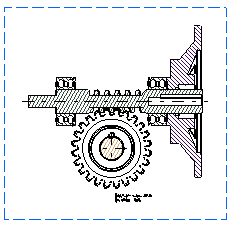
The selected element is not cut anymore.
-
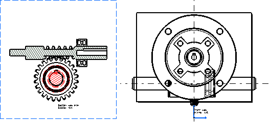
In the product's specification tree, select the Slow speed node.
Back to the drawing, the elements have been added to the Characteristics dialog box.
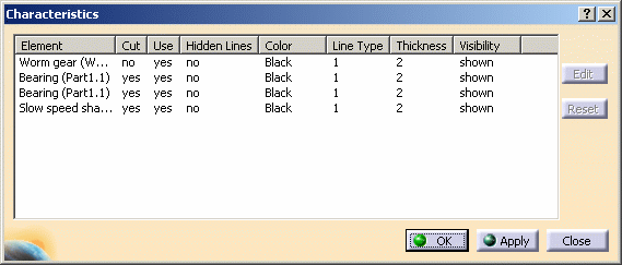
-
Select the last three elements in the list and click on the Edit button.
-
In the Editor dialog box select the red color in the Graphic properties drop down list.
-
Click OK to validate and exit the dialog box.
-
Back in the Characteristics dialog box, click Apply. A dialog box is displayed while the view is being re-computed.
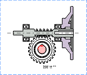
-
In the product's specification tree, press the Ctrl key and multi-select Motor adaptator and Roller bearing (Roller bearing.2).
Back to the drawing, the elements have been added to the Characteristics dialog box.
-
Select the last two elements in the list and click on the Edit button.
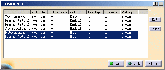
-
In the Editor dialog box, clear the Shown check box.
-
Click OK to validate and exit the dialog box.
-
Back in the Characteristics dialog box, click OK again. A dialog box is displayed while the view is being re-computed.
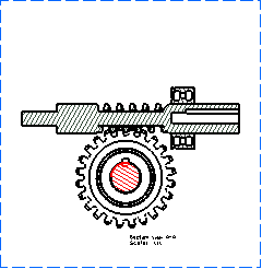

- In the Characteristics dialog box, the Reset button allows you to recover the values you had before changing information in the Editor dialog box.
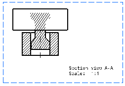
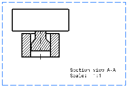
- In versions prior to V5 R13, in the case of faces overlapping
with un-cut elements, the pattern area used to go over the
projected faces and edges. From R13 onwards, the pattern area is
now limited to the face sectioned on the part, as shown below.
Previous behavior
New behavior
-
You can set the Drafting properties in the 3D document so that they are propagated in the 2D view: in the 3D document, right-click on the Bearing (Part1.1) instance.

-
Select Properties in the contextual menu and click on the Drafting tab.
The Drafting properties are displayed.

-
Select the Represented with hidden lines check box.
-
In the drawing, click Update
 .
.The element is represented with hidden lines in the view.
More About Overload Properties
There are two ways to activate the Drafting properties. You can either:
- go to Tools > Options and select the Apply 3D specifications check box in the View tab.
- right-click the view and select Properties, then check 3D spec in the View tab.
If you apply two dress-ups on an element, one manually (i. e. directly in the 2D view) and the other using the Overload properties option as presented below, the display priority is always given to the manual 2D dress-up.
![]()