- by entering the rotation angle and specifying the rotation axis
- by selecting a geometric element to define the rotation axis and entering the angle value (not described in this scenario)
-
Click the Translation or Rotation icon
 .
.
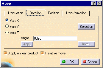
The Move dialog box is displayed.
-
Click the Rotation tab.
![]()
-
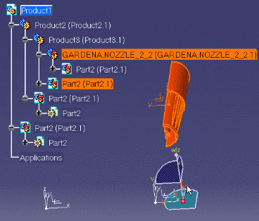
Select the component to be rotated, GARDENA,NOZZLE_2_2.1

![]()
![]()
-
Click one of the Axis options to specify the axis of rotation, e.g. the y axis.
-
Enter an angle of rotation in the Angle box , e.g. 90deg.
-
Click Apply to rotate the component
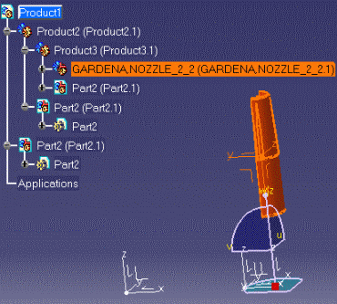
The selected component is rotated accordingly.
Note: you can apply this translation to other components. Simply select them and click Apply.
![]()
- Click Selection to define your rotation with respect to an element.
- Select an element to define the axis of rotation, e.g. an edge.
This procedure is not described in this scenario, please refer to Rotate
Components in Assembly User's Guide.

-
You can click Apply as many times as you wish to rotate the component to the desired position.
-
Click OK to close the dialog box.
Note: You can rotate constrained components by means of the Shift key and the compass.
![]()
