-
Click the Edge Of Part icon
 .
.
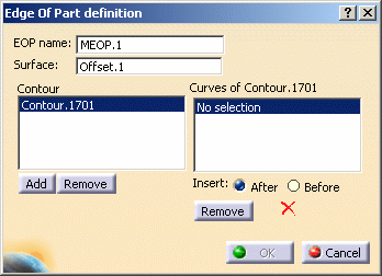
The Edge of Part definition dialog box is displayed. -
Change the MEOP name to MEOP.1.
-
Select the manufacturing surface (Offset.1).
The Contour field is updated.

-
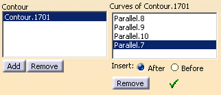
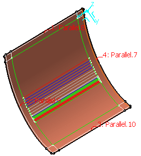
In the Curves of Contour.1701 field, select the curves so that they form the closed contour.
A green tip replaces the red cross.

- Use Add and Remove to add or remove a contour.
- Use Insert After, Before and Remove to modify the order of the curves as well as the contour.
-
Click OK to create the MEOP.
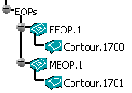
The MEOP.1 element is displayed in the specification tree under the EOPs node (below the EEOP.1 element created in the previous task) and contains the closed contour.

The following task precisely explains how to define the material excess.
![]()