|

|
1. |
Click the
Build Part button
 .
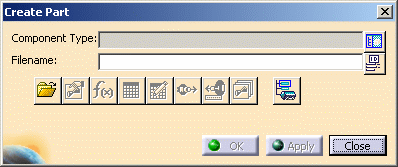
The Create Part dialog box appears. .
The Create Part dialog box appears.

|
|
2. |
Click the
Display Class Browser button next to the Component Type
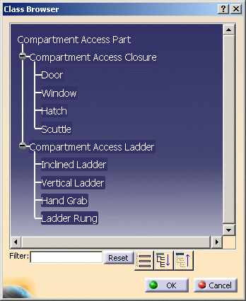
field. The Class Browser appears.

The Class Browser allows you to select the type of part you want to
create. |
|
3. |
Navigate to the part type you
want by clicking on the "plus" sign next to each directory, or by using
the three navigation buttons at the bottom. You can also filter for
certain types.
For instance, you can enter "ladder" in the Filter field and press
Enter to see all ladder types. Click OK after making your
selection
The Create Part dialog box displays again. |
|
4. |
(Optional) Click the Define
ID Schema button
 next to the Symbol Name field if you want the application to generate a
name for the part.
 |
|
5. |
Enter a name for the part in the Symbol Name
field and press Enter. Click Apply or OK. This
creates the part and displays it in the specifications tree. The part
has been created but it still does not have a graphic representation - it
has no "looks." Refer to Create Graphic
Representations for a Part. |
 |
To activate the
buttons on the Create Dialog box, you must activate the part by
selecting it in the specifications tree. You can also activate these
buttons by using the Open Exiting Part
 button,
which allows you to navigate to a directory containing an existing part. button,
which allows you to navigate to a directory containing an existing part.
The Define Properties button
 brings up the Properties box, allowing you to change properties if needed.
The Override Parameters button
 brings up a dialog box which allows you to override a parameter. When you
click on a parameter on the left side of the box and then click on the
arrow to bring it on the right side, that means the parameter can be
overridden. (See Change the Parameters of a Part.)
When you place this part, the application tries to determine a value for
that parameter. If it cannot, it prompts you to enter one.
Use the Design Table button
 to create a design table and associate it to the part you are creating.
For more information on this see the Infrastructure document - Advanced
Tasks - Using Knowledgeware Capabilities.
Use the Formula button
 to
create formulas and parameters. See the Knowledgeware document mentioned
above for more information. to
create formulas and parameters. See the Knowledgeware document mentioned
above for more information.
The Define Connector button
 allows you to add connectors.
The Associate attributes to
connectors button
 is not available in this product.
The Manage Representations button
 lets you create and manage graphic
representations.
 |
|
6. |
Save the part to the directory
specified in the resource management file by double-clicking the part and
using the File - Save menu. |
|
 |
![]()


![]() is not available in this product.
is not available in this product.![]() lets you create and manage graphic
representations.
lets you create and manage graphic
representations.![]()