|
|
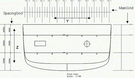
This task explains how to generate graphic replacement for reference plane systems. |
|
|
The sample XML file provided with this application is Structure_GraphicReplacement.xml. This file is located in ../OS/resources/standard/generativeparameters. Customizing parameters in this file affects the appearance of your drawings and is an administrator task. The reference planes that will be used for a given project are defined in an XML file pointed by a PRM resource:
For more information, see Project Reference Planes. |
|
|
Appropriate application licenses including one for Generative Drafting are required. |
|
|
For information on how to create views using generative view styles, how to set view style parameters or more generally on administering generative view styles, see the Generative Drafting User's Guide. |
|
You can customize generative view style parameters for the reference plane system. These parameters are shared by all structure applications. NOTE: Some parameters may be specific to Structure Functional Design and Structure Detail Design, and are not valid for Structure Design. |
|
|
|
In the sample XML file, generative view style parameters are located towards the bottom of the file under Structure. The file is organized as follows: |
 |
|
|
|
|
ShowReferencePlaneSystem Draws the reference plane system. Yes or No (Default). |
|
|
RestrictedToTheBoundingBox Restricts the reference plane systems to the generated object bounding box (Yes ). No is the default that draws the entire reference plane system line, except in the case of clipping. |
|
|
GridsetPosition Position of the reference plane systems according to the generated view. The default is 0: The reference plane systems are generated where the set of planes is located. A 1 specifies the position of the reference plane systems. |
|
|
GridSetSelection Specify where to place the grids:
|
|
|
Offset The horizontal offset to add between the generated view and the vertical reference plane system in millimeters. Default value is 35.0 mm. |
|
|
ShowMedian Median display switch. Yes or No. |
|
|
GridSetLineType Linetype used to draw the grid. Values are 1 thru 63. |
|
|
TickSize Size of the ticks, in millimeters, for the grid plane lines. Default is 2.0. |
|
|
AnnotationStyle Style of the annotation of the frames. No annotation = 0. |
|
|
AnnotationSize Size of the annotations. Default is 2.0. |
|
|
AnnotationFrame Type of annotation frame for the applied annotation. Default is None. |
|
|
AnnotationStep Step between two annotations. Default value is 1 (there is an annotation on each stick). |
|
|
AnnotationStart The first annotation position. Default is -100 to display all frames within the bounding box. |
|
Elevations
|
|
|
StandardFrame Indicate how to display standard frames. See description of parameters. |
|
|
WebFrame Indicate how to display web frames. See description of parameters. |
|
|
SpecialFrame Indicate how to display special frames. See description of parameters. |
|
|
AFT Indicate how to display AFT frames. See description of parameters. |
|
|
MFZ Indicate how to display MFZ frames. See description of parameters. |
|
|
|
|
|
|
SpacingGridStyle The style of the spacing grid to be displayed. |
|
|
ShowSpacingGrid Draws the spacing grid. |
|
|
Offset1 The offset to add between the generated view and the median in millimeters. Default is 20.0. |
|
|
Offset2 The offset to add between the generated view and the median in millimeters. Default is 30.0. |
|
|
TextPosition The position of the text relative to the gradation. Default is Below. |
|
|
MidshipsSymbolDisplay Draws the midship symbol. Yes or No. |
|
|
MidshipsSymbolChapterName The name of the chapter containing midship symbol within the Drawing Symbol Structure Catalog (refer to PRM file). Default value is MTOs. |
|
|
MidshipsDetailName The name of the detail within the catalog to instantiate for Midships Detail Name. Default value is MidShip. |
|