 |
This task deals with the
following topics:
|
| |
|
 |
Generative view styles make
it possible to customize the appearance of drawings via a set of
parameters defined in an XML file, DefaultGenerativeStyle.xml. Some
generative view style parameters are specifically available to produce
customized drawings from parts designed in the Generative Sheetmetal
Design workbench. It is the administrator's job to provide suitable
styles. |
| |
|
 |
For additional information on how to customize
parameters, or more generally on generative view styles, see the
Generative Drafting User's Guide. The Administration Tasks chapter
deals with the administration of generative view styles. The Basic Tasks
> Generative View Styles chapter explains how to use generative view
styles. The
SheetMetal Parameters task explains how to customize generative view
styles for Generative SheetMetal Design. |
| |
|
 |
Open the
SheetMetalDrafting1.CATPart document.
Make sure you have an appropriate Generative Drafting license.Specify
your settings before you start: select Tools -> Options
-> Mechanical Design -> Drafting -> Administration tab, and uncheck
Prevent generative view style usage.
This activates generative view style functionalities. |
| |
|
 |
-
Select Start -> Mechanical Design -> Drafting.
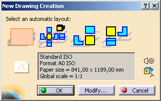
The New Drawing Creation dialog box appears. The empty sheet
layout is pre-selected.
-
Simply click OK. You switch to the Drafting
workbench and an empty drafting sheet is created.
-
For ease of use, tile the windows horizontally using
the Window -> Tile Horizontally menu item.
-
Click Unfolded
View
 in the Projections toolbar from the Generative Drafting workbench. The
Generative View Style toolbar is automatically displayed.
-
Select one of the available styles from the list,
DefaultGenerativeStyle in this case.
-
Return to the 3D document and select a plane surface on
the sheet metal part. The sheet metal reference wall plane
is used automatically.
A preview of the view is displayed in the drawing.
-
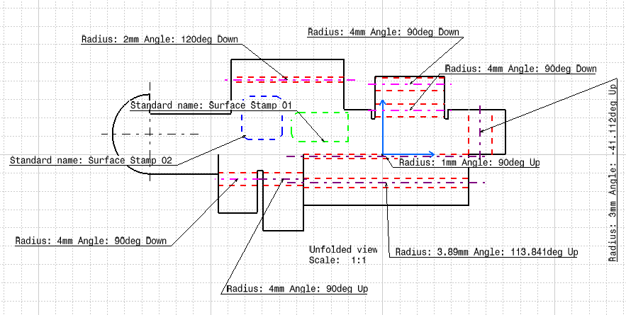
Click in the drawing to validate the view creation. The
unfolded view is created, using the sheet metal-specific styles defined
by the chosen generative view style. Here, the BTLs (Bend Tangent
Lines) and the stamps are projected in the view, as specified in the
DefaultGenerativeStyle.xml file.
Note that the axis of upward and
downward bends are represented in a different color, as well as upward
and downward stamps.
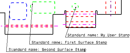
Annotations containing the bend's direction, radius and
angle value, as well as the standard name of the stamp, if any, can
also be displayed on the drawing, provided your administrator has
activated the corresponding parameters contained in the
DefaultGenerativeStyle.xml file.
 |
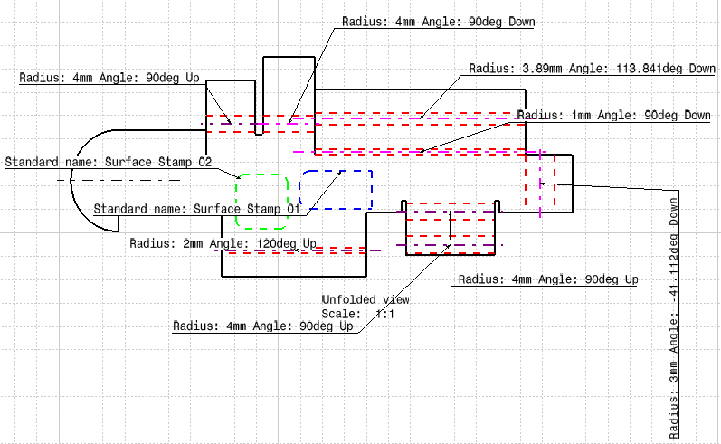
The bend axis and bend annotations are
displayed according to the orientation of the part. |
|
| |
|
|
|
 |
Save the
DefaultGenerativeStyle_customized.xml file and place it in
install_root/resources/standard/generativeparameters. |
 |
-
Select Start -> Mechanical Design -> Drafting
to open an empty drafting sheet.
-
Click OK
and tile the windows horizontally using the Window -> Tile
Horizontally menu item.
-
Click Unfolded View
 in the Projections toolbar from the Generative Drafting workbench.
-
Select the
DefaultGenerativeStyle_customized style in
the Generative View Style toolbar that is automatically displayed .
-
Return to the 3D document and select the surface on the
sheet metal part.
-
Click in the drawing to validate the view creation.
The unfolded view is created with annotations specifying the parameters
of bends and stamps. These parameters depend on the
orientation of the part.
|
|
 |


