This task explains how to define a corner relief locally on a set of supports.
For the Generative Sheetmetal Design workbench, open the CornerRelief02.CATPart document.
The part needs to be unfolded prior to creating the corner relief.
-
Click Corner Relief
 .
.The Corner Relief Definition dialog box is displayed. 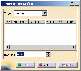
-
Select the supports on which a corner relief should be created (here we chose Surfacic Flange.1 and Surfacic Flange.2)
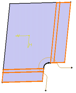

A notch was defined on the web profile between the two fillets' flanges; so that flanges do not intersect. This operation enables to prepare the web as to create the flanges that will be later used to define the corner relief. - By default the Circular Profile
 is active
in the Corner Relief Definition dialog box.
1. Define the default radius: it is equal to the bend radius + the thickness.
In our example, we defined a radius of 15 mm.By default the corner relief center is located at the intersection of the bend axes. You can select a point as the circle's center. 2. Select the vertex between the two flanges: it will be the center of the corner relief.
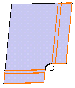
3. Click OK in the Corner Relief Definition dialog box.
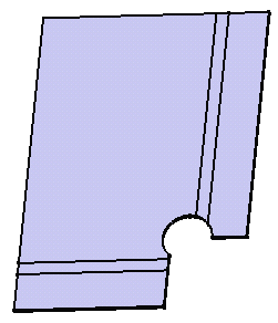
The created element (identified as Corner Relief.xxx) is added to the specification tree. - Select the User Profile
 using the down
arrow.
- Select the sketch, directly in the 3D geometry.
- Click OK in the Corner Relief Definition dialog box.

You can use the Catalog icon  to open the
Catalog Browser.
For more information on catalogs, refer to the Component Catalog Editor User's Guide.
- By default the Circular Profile
-
Fold the part to check the corner relief in 3D.
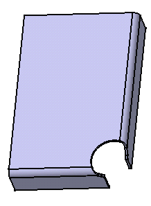
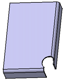
Folded user corner relief Folded circular corner relief 
The Supports Redefinition checkbox enables to redefine the supports' sides thus adding matter to these supports.
In that case, the created element (identified as Corner Relief.xxx) appears before the supports in the specification tree.

Please note that checking this button means that the corner relief replaces the surfacic flange's side. This side must therefore exists: when creating the surfacic flange, do not define the side as None. 
-
In hybrid context, when checking Supports Redefinition, the Surfacic flanges are hidden in the 3D since the define in work object parameter is applied to the corner relief.
-
Moreover, the sketch is not aggregated anymore under the corner relief in the specification tree.
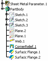
Yet, if you open a part created in a previous release, the specification tree will be displayed accordingly to the previous behavior.
Fore more information about Hybrid Design, refer to the Hybrid Design section.
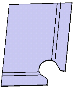
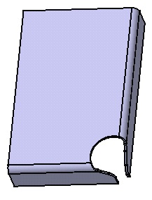
Unfolded user corner relief
with redefined supportsFolded user corner relief
with redefined supportsThe image below shows two surfacic flanges creating with Angle as support type.
The two blue dotted lines represent the limits of the unfolded surfacic flanges.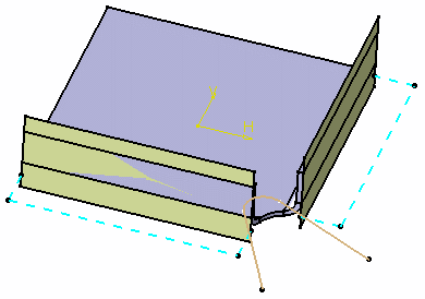

- The creation of a corner relief with supports redefined is not possible as it is not located within the limits of the unfolded flanges.
- A corner relief with supports redefined cannot be created if its profile implies adding matter to the web.
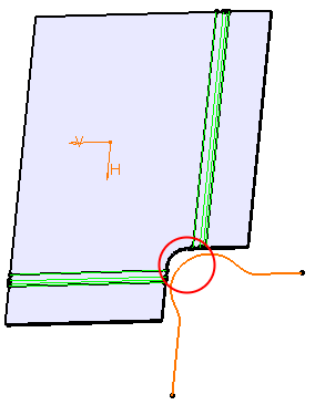
-
![]()
