 |
This task explains how to browse the SheetMetal catalog
and instantiate its components. The catalog lets you store the available
profiles, therefore providing a method to position the profile in the
part.
This command is available with the CutOut and the
Corner Relief
functionalities.
Let's take an example with the CutOut functionality. |
|
For more information on catalogs, refer to the
Component Catalog Editor User's Guide. |
 |
Open the
CutOut1.CATPart document. |
 |
-
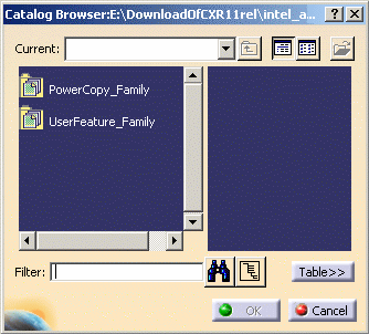
Once in the CutOut Definition dialog box, click Catalog  . .
-
Double-click a family from the list to display its
components.
| Here we chose the UserFeature_Family. |
-
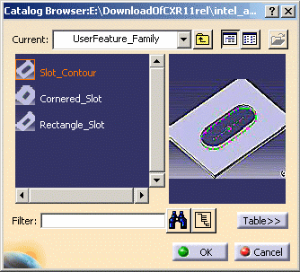
Click a component to see its preview.
|
Here we chose Slot_Contour. |
| |
|
 |
| |
-
Click the Table>> button to show/hide the
catalog descriptions and keywords. By default, the table is hidden.
-
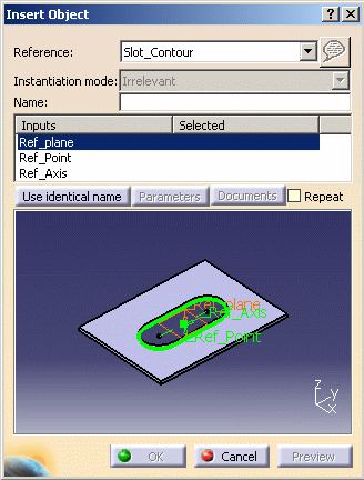
Instantiate the component by double-clicking it.
-
Select the required inputs: plane, point, and axis.
| The Insert Object dialog box is displayed. |
 |
-
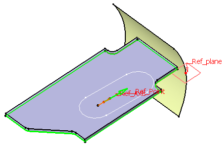
Click Preview to see the resulting profile in the 3D
geometry.
-
Click OK in the Insert dialog box.
| The selected profile appears in the Selection field. |
| |
 |
-
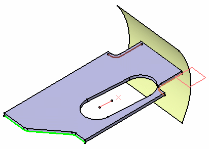
Click OK.
 |
| |
| The created element (identified as Cutout.xxx) is
added to the specification tree. |
| |
 |
You may need to reverse the direction of the cutout to create
it. |
| |
|
 |
Once the profile is instantiated in the default catalog, its
path is automatically set in the Standard Profiles Catalog Files
field. See Customizing Settings in the Customizing chapter. |
| |
|
A new panel now allows you
to select alternate document access methods.
See Opening Existing Documents Using the Browse Panel in CATIA
Infrastructure User Guide. |
|
|
 |
