- to split a mesh in several meshes (displayed in different colors
below):

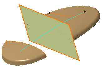
- and/or trim portions of the mesh delimited by curves, planes, surfaces
or other meshes:
- The mesh must be exempt of Non Manifold problems,
even on non-active areas.
You should use the Mesh Cleaner. - Keep the portion of curves not taken into account at intersections as short as possible.
- For a better understanding, the colors of the mesh portions have been changed.
-
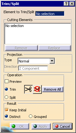
Select the mesh to trim or split. It can consists of several cells.

-
Select the Cutting elements .
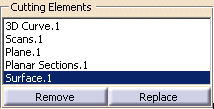
They can be:
- scans,
- curves,
- planes,
- surfaces,
- meshes.
Those input elements are highlighted in the graphic area and listed in the dialog box.
To remove a cutting element, select it in the dialog box list and push the Remove button.
To replace a cutting element with another, select is in the dialog box list,
push the Replace button and select the new cutting element.
To define an area, the projection curves of the cutting elements must intersect
each other or intersect free edges.- This case defines two areas:
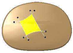
- This case defines four areas:
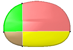
- This case is not valid: the projection curve does not intersect
any free edge.

- In some cases, changing the Projection type may solve the problem.
-
Select the Projection type

When scans or curves are used as cutting elements, those entities are close to the mesh but not on the mesh.
To compute the intersection, it is necessary to project those scans or curves on the mesh to
create intersection curves.
Four projection options are proposed:- View: the projection is done along the view direction,
- Compass: the projection direction is defined using the compass,
- Normal: the projection is normal to the mesh,
- Along a direction: the projection is done along the direction defined by the user.
The projection option applies to all cutting elements.
-
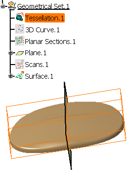
Select the Preview check box if you want to see the projection of the cutting elements on the mesh.

This is an example of the Preview of a plane.
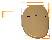

For better performances you should not activate the preview unless absolutely necessary. -
Decide whether you want to trim or split the mesh:
If you want to split the mesh:
- Make sure the Split option is selected. This makes the Apply button available.
- Click Apply. The action creates several new meshes.
If you want to trim the mesh: -
Make sure the Trim option is selected.
This makes the scissors and crossed-scissors available.

-
Use the scissors or crossed-scissors to define the portions to be kept or removed:
-
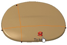
Click the scissors button and pick the area(s) you want to remove,
-
Click the scissors button and pick the area(s) you want to remove,
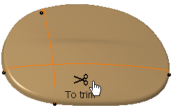
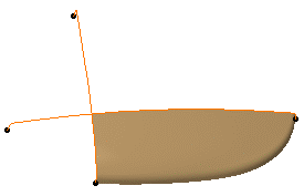
Result: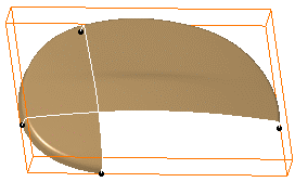
-
-
or click the crossed-scissors button and pick the area(s) you want to keep.
-
or click the crossed-scissors button and pick the areas you want to keep.
Result:
-
- Click a scissors or crossed-scissors icon to delete one occurrence, or use the contextual menu.
- Click Remove All to delete all occurrences, or use the contextual menu.

- Unselected areas have the opposite status.
- You can not mix instances of scissors and crossed-scissors.
A contextual menu is available on scissors and crossed-scissors:
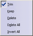
- Delete: Deletes the occurrence,
- Delete All: Deletes all occurrences,
- Invert All: Replaces all occurrences of scissors by crossed-scissors and vice-versa.
-
-
Select a Result option:

-
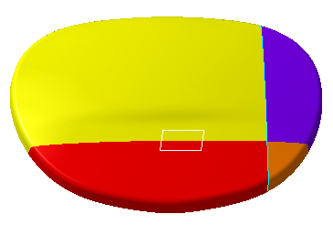
if you check Distinct, the output meshes will be distinct elements,
-
If you check Grouped, the new meshes will be cells grouped in a single body.
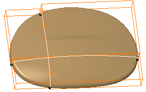
-
-
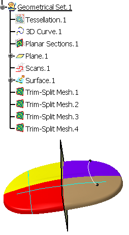
Keep Initial controls whether a new mesh is created in the specification tree or if the input mesh is replaced
by another when the command is executed.If Keep Initial is checked: -
the input mesh is sent to the NoShow and remains in the specification tree,
-
the output meshes are created in the specification tree and the graphic area:
-
Distinct is selected
- Grouped is selected
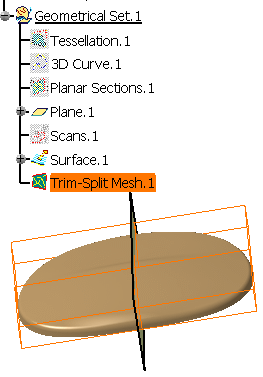
-
If Keep Initial is not selected:
- if Distinct is selected, the input mesh is removed
from the specification tree,
the output meshes are created in the specification tree and the graphic area.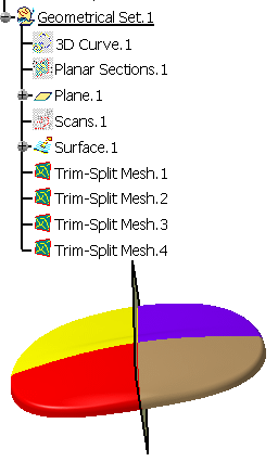
- if Grouped is selected, the result multi-cells mesh
replaces the input mesh:
- the input mesh is removed from the graphic area but its name remains in the specification tree,
- the result multi-cells mesh is created in the graphic area and under the name of the input mesh in the specification tree.
-
-
Click Apply to preview the result.
-
Click OK to validate and exit the action.
![]()
