|
|
This section show you how to measure
properties.
The following topics are covered:
|
Measuring Properties
|
 |
This task explains how to measure the properties associated
to a selected item. |
 |
Insert the following sample model files: ATOMIZER.model,
BODY1.model, BODY2.model, LOCK.model, NOZZLE1.model, NOZZLE2.model,
REGULATION_COMMAND.model, REGULATOR.model, TRIGGER.model and VALVE.model.
They are to be found in the online documentation file tree
in the common functionalities sample folder cfysm/samples. |
 |
-
Switch to Design Mode (Edit > Representations >
Design Mode).
-
Set View > Render Style to Shading with Edges.
 |
You cannot use this command, if Shading only is
selected |
-
Click Measure Item
 .
In DMU, you can also select Analyze > Measure Item from the
menu bar. The Measure Item dialog box appears. .
In DMU, you can also select Analyze > Measure Item from the
menu bar. The Measure Item dialog box appears.
|
By default, properties of active products are measured with respect
to the product axis system.
Properties of active parts are measured with respect to the part axis
system. Note: This distinction
is not valid for measures made prior to Version 5 Release 8 Service
Pack 1 where all measures are made with respect to the absolute axis
system.
|
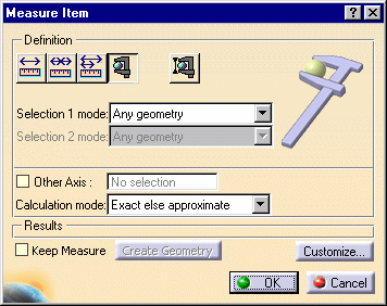
-
Set the desired measure mode in the
Selection 1 mode drop-down list box.
-
Set the desired calculation
mode in the Calculation mode drop-down list box.
-
Click to select the desired item.
|
|
Note: The
appearance of the cursor has
changed to assist you. |
|
 |
|
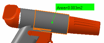
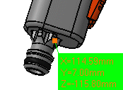
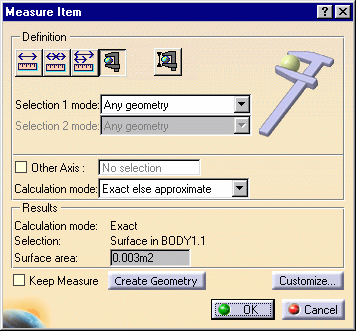 The dialog box gives information about the selected
item, in our case a surface and indicates whether the result is an
exact or approximate value. The surface area is also displayed in the
geometry area.
The number of decimal places, the display of trailing
zeros and limits for exponential notation is controlled by the Units
tab in the Options dialog box (Tools > Options, General > Parameters and Measure). For more information, see
the Infrastructure User's Guide. |
-
Try selecting other items to measure associated
properties.
|
|
Note: For reasons
of legibility, angles measured by Angle by 3 points or on an arc of
circle of less than 0.02 radians (1.146 degrees) are not displayed in
the geometry area. |
|
") |
|
 |
-
Click OK when done.
|
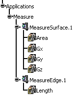
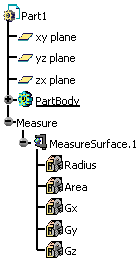
If you checked the
Keep Measure option in the Measure Item dialog box,
your measures are kept as features and your specification tree will
look something like this if properties of the active product were
measured.
 |
|
Or like this, if properties were those of the active
part.
 |
|
|
Notes:
-
If the product is active, any measures made on the
active part are placed in No Show.
-
Elements placed in No Show are taken into account
in measure operation.
|
|
Some measures kept as features are
associative. In Design
Mode, if you modify a part or move a part in a product structure
context and the measure is impacted, it will be identified as
not up-to-date in the specification tree. You can then update it
locally have it updated automatically.
When measures are used to valuate parameters, an
associative link between the measure and parameter is
created. Measures can also be used in
formulas.
|
|
Measuring Properties in a Local Axis System
|
|
|
An Other Axis option in the dialog box lets you
measure properties in a local axis system.
This type of measure is associative: if you move the axis
system, the measure is impacted and can be updated. |
|
|
You will need a V5 axis system. |
|
|
-
Select the Other Axis check box in the Measure
Item dialog box.
-
Select a V5 axis system in the specification tree or
geometry area.
-
Make your measure.
|
Measure made with respect to local axis system: |
|
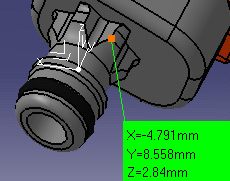
Same measure made with respect to absolute axis system: 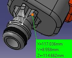
Note: All subsequent measures are made with
respect to the selected axis system. |
-
To change the axis system, click the Other Axis field and
select another axis system.
-
To return to the main axis system, click to clear the
Other Axis check box.
-
Click OK when done.
Surfaces and Volumes
The center of gravity value result differs,
depending on the command you are using (Measure Inertia or Measure
Item). This is a standard behavior as:
Measure inertia takes into account the material
applied on parts and/or products whereas,
Measure Item calculates the geometrical center of
gravity without taking into account the applied material.
Measures and Knowledge
When performing a measure operation, Knowledge parameters
are created along with the calculated values. You
customize their display in the Measure customization dialog box.
Note: No knowledge parameters are created for the
equation of a plane.
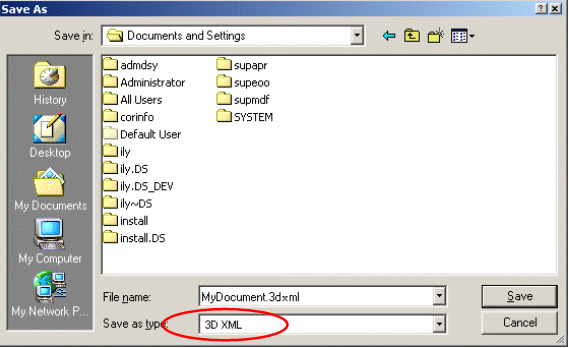
3D XML and Measure Item
3D XML format is now supported, which means you can:
Note: The text properties (i.e. Color, Font and size for the
Measure Item in 3DXML will not be retrieved when saving in 3D XML).
Important
-
Neither Visualization Mode nor cgr files permit selection
of individual vertices.
-
In the No Show space, Measure Item
is not accessible.
-
Measures performed on sheet metal features provide wrong
results. In unfolded view, volume elements are not taken into account
when measuring Part Bodies.
-
Measures are not associative when switching between
folded view and unfolded view (using the Fold/Unfold
 in the Sheet Metal toolbar).
-
When measuring an entity with a given dimension, all
geometries contained with lower dimension are ignored for the
calculation. For example, edges, surfaces are ignored under a PartBody
if this PartBody contains a volume (see illustration below, i.e. the
difference is illustrated in Generative Shape Design and Part Design
workbenches).
|
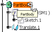
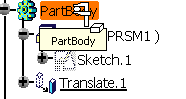
When translating a PartBody containing a measure in
Generative Shape Design
(using Insert > Operations > Translate...) this is what you
obtain: |
|
|
|
|
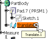
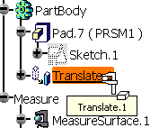
When translating a PartBody containing a measure in
Part Design (using Insert > Transformation Features >
Translation) this is what you obtain: |
|
|
|
|
|

|