|
|
This task describes how to move the manikin's segments
using the inverse kinematics' commands in the Manikin Posture toolbar:
|
||||||||
|
|
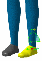
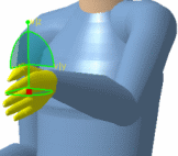
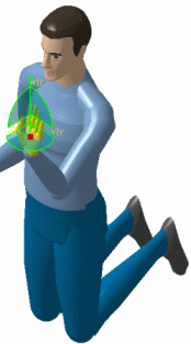
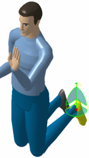
Inverse kinematics is a very intuitive tool for quickly positioning the manikin in its environment. This command is based on Fix IK constraints creation and activation on the dedicated segments. The principle is simple. The selection of a segment activates a constraint. This constraint can be used for fixing a segment or for moving it. No constraint will be created automatically without previously selecting the appropriate segment. Before, when the pelvic segment's control point was activated, constraints were created automatically for fixing the feet. The reason for this change is to gain the ability to relocate the manikin without keeping the feet at the same place. | ||||||||
| This task also describes how to use a 3D mouse to manipulate manikins while in IK mode. The 3D mouse does not replace the regular mouse and keyboard but is used as an additional tool. For more information on how to use a 3D mouse with V5 products, please see "Moving Objects Using the 3D Mouse" in the Infrastructure User Guide. | |||||||||
|
|
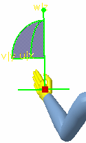
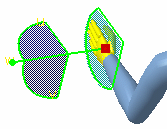
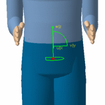
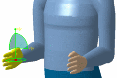
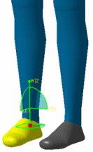
IK Worker Frame mode This mode behaves in the same manner except the compass is oriented in the worker (global) frame.
IK Segment Frame mode
|
||||||||
|
|
IK Worker Frame mode |
||||||||
|
|||||||||
|
|
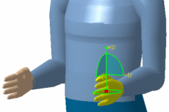
IK Segment Frame modeThis
|
||||||||
|
|||||||||
| When finished, drag the compass back to the empty space or select View > Reset Compass from the main menu. | |||||||||
|
|
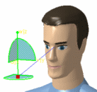
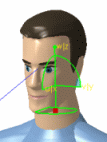
Using the 3D mouse for IK modeThe 3D mouse, supported by V5, is a new method for moving the manikin in IK mode. IK Worker Frame modeThe manikin coordinate system is used as the reference when using the 3D mouse to manipulate the compass in this mode. The spatial representation appears as if the user is standing behind the manikin, placing his hand on the top of the manikin's hand, foot, etc. When you push the 3D mouse button forward, the selected segment (foot, hand, head, etc.) will move forward. Moving the mouse upward produces an elevation, etc. All rotations are blocked in IK Worker Frame mode. IK Segment Frame modeIn this mode, the 3D mouse is used to produce rotations of any segment. The spatial representation appears as if the user is standing behind the manikin, placing his hand in the same orientation as the manikin's hand, foot, head, etc. The Manikin eyes follow the 3D compass with Reach and IK ModeThis proposes a more natural behavior for the manikin's vision when it is performing a reach or IK on an object. The vision of the manikin is directed to the object the manikin is trying to pick up, which would be more like human behavior. |
