 |
This task shows you how to match
a mono-cell non-relimited surface to at least two and at most four
other surfaces. The source surface's edges will be deformed to match the
target curves on surfaces, taking continuities into account. |
 |
Some options are only available in FreeStyle
Optimizer. |
 |
Open the
FreeStyle_Part_32.CATPart document. |
 |
-
Click the Multi-Side Match Surface icon
 . .
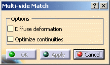
The Multi-side Match dialog box is displayed.
-
Set the deformation options:
-
Diffuse
deformation: if checked, the deformation is spread over the
whole matched surface, not only to a limited number of control points.
-
Optimize
continuities: if checked, the deformation is done optimizing the
continuities as defined by you rather than according to the control points
and mesh lines.
|
| |
 |
|
-
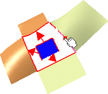
Select the first edge of the surface to be matched.
It is automatically detected as you move the pointer then highlighted
once selected.
|
| |
|
|
-
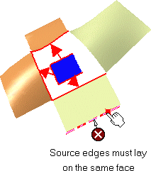
Select the target curve for the first selected edge.
An arrow is displayed indicating which source edge is to be matched to
which target curve.
Note that in case an incorrect edge is detected, a
contextual message helps you select the adequate target curve.
|
| |
|
|
-
Click the Continuity icon
 from
the dashboard, to visualize texts on the geometry. from
the dashboard, to visualize texts on the geometry.
Then right-click the texts to modify the continuity type (point,
tangency, curvature) or to increase/decrease the edge order.
|
|
-
Continue selecting pairs of source and target curves to
be matched, as needed.
-
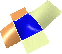
Click Apply to visualize the matched surface.
If you already selected four source edges and four curves, the match
is automatically computed.
|
| |
 |
|
-
Click OK to create the multi-side match surface.
|
 |
- All source edges must belong to the same surface.
- Only a complete surface, i.e. that has not been previously relimited,
can be matched.
- Target curves necessary are surface boundaries or isoparametric
curves, therefore laying on a surface. They cannot be curves created in
space.
- Checking the U, V Orders
 icon from the Dashboard, displays texts indicating the resulting surface
order along U and V.
Right-click these texts to choose a new order value.
- A surface can also be matched onto a relimited surface.
- The match takes into account continuities and order, but also
existing geometric configurations.
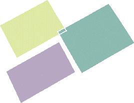
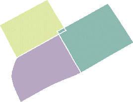
For example, in the example below, the two target surface overlap. In
this case, the system automatically relimits the matched surface where
the target surfaces overlap:
|
|
|
 |
 |
Available capabilities from the Dashboard are:
temporary analysis,
U, V Orders, auto
detection (Snap On Edge option only), continuity, and furtive
display (control points are displayed on both the surface to be matched and
the target surfaces). |
![]()


![]()