 |
They are of two kinds:
- Views/annotation
planes are specified around the geometry for automatically generating
the corresponding views, sections and cuts of the 2D drawing.
- Extraction views are particular
kinds of views, specifically aimed at preparing 2D extraction.
-
|
 |
Views/Annotation Planes
|
| |
The views/annotation planes are by default
displayed in the 3D with a dashed frame that is resized to always frame all
the annotations that are linked to it. When the view/annotation plane is
active (the preferred view to receive newly created annotations), its
origin and axis system is also displayed and the dashed frame is also
resized to frame the axis system origin.
Note that when creating a new view/annotation plane by selecting a
planar surface, the origin that is chosen is the part/product origin. If
you want to choose the origin (and the axis orientation) of the view, you
have to select an existing axis system while creating.
Note also that the position and orientation coordinates of a given
annotation that are displayed in the Position And Orientation
toolbar and in the Position region of the Text tab
page of the annotation properties are expressed in the view axis system. |
| |
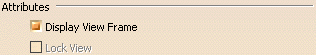
You can control the 3D display of the dashed
frame of a view by modifying its Display View Frame property.
See Editing View/Annotation Plane Properties. |
| |
 |
| |
For more information, see 3D Annotations Infrastructure settings and/or
Functional Tolerancing & Annotation settings in Tools > Options. |
| |
Three types of annotations planes are
available:
|
| |
Creation Rules
|
| |
The views/annotation planes are created using
the following rules:
- The views/annotation plane axes take into account:
- The selected plane normal.
- The view direction of the viewer.
- Axes of the document.
- When using a reference plane, the views/annotation plane is always
parallel to the reference plane but its X and Y axes are not necessarily
parallel to the reference plane edge directions. If you like to keep
these directions, you must associate an axis system to the reference
plane before use it for the views/annotation plane creation.
|
| |
Front View/Annotation Plane
|
|
A front view/annotation plane allows you
to manage 3D annotations:
- Located in planes both parallel to this view/annotation plane and in
the background and foreground spaces bounded by this view/annotation
plane (or in any plane of the direction of planes defined by this
view/annotation plane),
- Related to the geometry finding an intersection with this
view/annotation plane,
- Lying on/belonging to this view/annotation plane.
|
|
This view/annotation plane allows you to
specify a particular view/annotation plane for generating embedded 2D
front/projection views, in the Generative Drafting workbench, during the 2D
extraction of the 3D part and of the 3D annotations. |
| |
Annotations can be translated along the z
axis of its local coordinate system.
Negative and positive z values can be used to define the translation, since
the front view/annotation plane will be used for the extraction of
front views in the Generative Drafting workbench. |
| |
See Creating a
Front View. |
| |
Section View/Annotation Plane
|
|
A section view/annotation plane allows you to
manage 3D annotations:
- Located in planes both parallel to this view/annotation plane and in
the background space bounded by this view/annotation plane,
- Related to the geometry finding an intersection with this
view/annotation plane,
- Lying on/belonging to this view/annotation plane.
|
|
This view allows you to specify a particular
annotation for generating embedded 2D section views, in the Generative
Drafting workbench, during the 2D extraction of the 3D part and of the 3D
annotations. |
| |
Annotations can be translated along the z
axis of its local coordinate system.
Only negative z values can be used to define the translation, since the
section view/annotation plane will be used for
the extraction of section views in the Generative Drafting workbench. |
| |
See Creating a
Section View/Annotation Plane. |
| |
Section Cut View/Annotation Plane
|
|
A section cut view/annotation plane allows
you to manage 3D annotations:
- Only related to the geometry finding an intersection with this
view/annotation plane,
- Related to the geometry finding an intersection with this
view/annotation plane.
|
|
This view allows you to specify a particular
annotation for generating embedded 2D section views, in the Generative
Drafting workbench, during the 2D extraction of the 3D part and of the 3D
annotations. |
| |
Annotations cannot be translated along the z
axis of its local coordinate system (z=0), since the section cut
view/annotation plane will be used for the extraction of section cuts in
the Generative Drafting workbench. |
| |
See Creating a
Section Cut View/Annotation Plane. |
| |
Extraction Views
|
|
|
Extraction views are particular kinds of
views. They specifically aimed at preparing the following types of views
for 2D extraction:
- aligned section views/section cuts
- offset section views/section cuts
Extraction views are made up of several annotation planes (of the same
type). You can create annotations in each view/annotation plane making up
the extraction view. You will then be able to extract this extraction view
to 2D in the Generative Drafting workbench, as well as all annotations
defined in each component section view.
Extraction views, no matter their type, use a cutting profile as cutting
plane. |
| |
Aligned section views/section cuts
|
| |
An aligned section view/aligned section cut
is created from a cutting profile defined from non parallel planes. In
order to include in a section certain angled elements, the cutting plane
may be bent so as to pass through those features. The plane and feature are
then imagined to be revolved into the original plane. Aligned section
views are made up of several section views/annotation planes, as described
in Section View/Annotation
Plane above.
Aligned section cuts are made up of several section cut views/annotation
planes, as described in
Section Cut View/Annotation Plane above. |
| |
Offset section views/section cuts
|
| |
Offset section views/offset section cuts let
you show several features that do not lie in a straight line by offsetting
or bending the cutting plane, which is often desirable when sectioning
through irregular objects. Offset section views are made up of several
section views/annotation planes, as described in
Section View/Annotation Plane
above.
Offset section cuts are made up of several section cut views/annotation
planes, as described in
Section Cut View/Annotation Plane above. |
|
|
|
 |
3D Preview of view
|
|
|
 |
|
 |
-
-
-
-
-
-
|