You can also duplicate by offset one of the following: an edge, a face (all the boundaries of this face are offset) or a geometrical feature (for example, by selecting a join or another sketch in the specification tree).
Select a topic:
Offsetting 2D Geometry
-
Click Offset
 from the Operations toolbar (Transformation
subtoolbar).
OR
-
Select the Insert >Operation>Transformation>Offset command from the menu bar.


-
There are two possibilities, depending on whether the line you want to duplicate by offset is already selected or not:
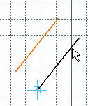
- If the line is already selected, the line to be created appears immediately.
- If the line is not already selected, select it. The line to be created appears.
-
Select a point or click where you want the new element to be located.
The selected line is duplicated. Both lines are parallel.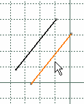
- If you were offsetting circles or arcs, these two circles would be concentric.
- If Geometrical Constraints
 and Dimensional Constraints
 are active in the Sketch tools toolbar when offsetting an
element, constraints are automatically created, based on the type of
element you are offsetting. Thus, if you move an element, or change
its geometry, the other element will be moved or modified accordingly.
Using offset tools
You can also apply one or more offset instances to profiles made of several elements:
- by using tangency propagation or point propagation,
- by creating an offset element that is tangent to the first one,
- by creating several offset instances.
If the multi-selected elements do not make up a closed profile, the offset will be applied to the selected elements only. As a result, you will have as many offset elements as the first multi-selected elements.
Previews are not available when creating several offset instances (i.e. when the value in the Instance(s) field of the Sketch tools toolbar is higher than one).
-
Click Offset
 from the Operations toolbar (Transformation
subtoolbar).


-
Select the desired option from the displayed Sketch tools toolbar. (These options are described further down in this section).
-
Select the element you want to offset and if needed, enter the desired number of instances. The element to be created is previewed.
-
Select a point or click where you want the new element to be located.
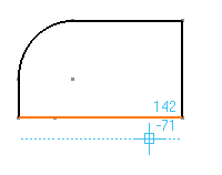
To offset a single element:
Activate No Propagation
![]() .
.
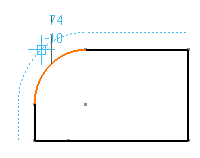
To offset an element and elements which are tangent to it:
Activate Tangent Propagation
![]() .
.
To offset an element using Point Propagation:
Activate Point Propagation
![]() .
.
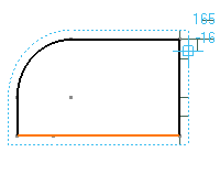
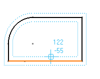
To offset an element symmetrically to another:
Activate Both Side Offset
![]() .
.
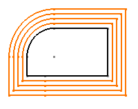
To offset and duplicate multiple elements:
Type the number of elements you want to create in the Instances field.

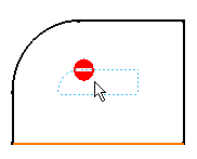
Drafting Workbench
You can create offset geometry using 2D component elements and dress-up elements (axis lines, center lines and threads). Note that by doing this, you will not create offset 2D components or dress-up elements, but you will create offset geometry.
- You can offset them only element by element.
- You cannot offset complex curves.
- This will only work if you first select the command and then the element to offset.
Offsetting 3D Geometry
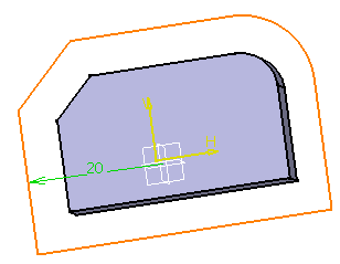
You can create an associative offset with a 3D element.
Open the Offsetpad.CATPart document.
-
Click Offset
 from the Operations toolbar (Transformation
subtoolbar).
 -
Select the 3D surface to offset, Face.1 for example. The profile to be created is previewed.
-
You can do one of the following:
- specify the offset position or value in the Sketch tools toolbar and press Enter to validate.

- Move the cursor till the correct offset appears in the sketch, then click to validate the position.
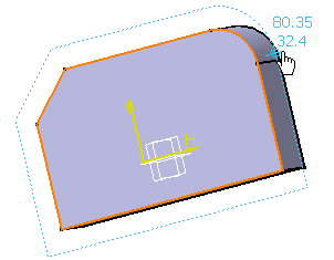
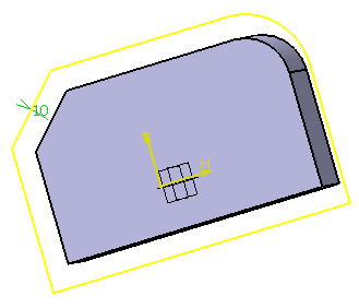
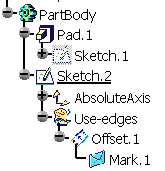

- When offsetting a face, if there is an intersection between the face and the sketch plane, by default, it is this intersection which is offset (rather than the projection of the face edges). In this case, if you want to offset the projection of the face edges, you can modify the offset as explained in the section below.
- You can offset the intersection between a face and a sketch plane without explicitly creating this intersection.
- lf you offset a multi-domain face, the face that is closer from the cursor is offset.
- If you isolate a composite mark, as many simple geometry elements as the mark was containing are created, and associativity will not be available anymore.
Modifying a 3D Geometry Offset
-
Double-click the offset in the specification tree or on the sketch. The Offset Definition dialog box is displayed.
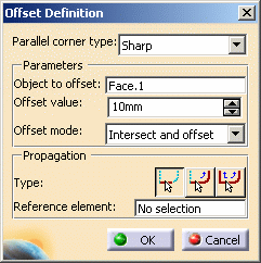
In this dialog box, you can modify the offset definition.
- Parallel corner type: specifies whether corners should be round or sharp (when applicable).
Parameters
These options let you specify the offset parameters.
- Object to offset: indicates which 3D element is offset. To offset another element, select this field and then select the new element in the sketch.
- Offset value: indicates the offset value. You can modify it by typing a new value in this field.
- Offset mode: when offsetting a face, specify whether you want to intersect and offset or to project and offset the face by selecting the appropriate option from the list.
Propagation
These options let you offset a 3D element using the propagation of an edge.
- Type: specifies what type of offset propagation should be applied to the selected reference element: No propagation, Tangent propagation, or Point propagation. Click the appropriate icon.
- Reference element: indicates which edge should be used as a reference for the propagation. Select this field and then select the reference edge in the sketch.
-
In the Offset value field, type 20mm.
-
Choose Project and offset from the Offset mode field.
-
Click OK to validate. The offset is modified.
- Only 3D elements can be offset with associativity.
- There is no propagation on 3D edges.
- Typing a negative offset value reverses the offset direction.
- Multi-domain elements cannot be offset in one shot.
- If you apply the Parents/Children... command to a sketch containing an offset obtained after selecting a face or an edge, the Parents command shows the last solid feature that modified the offset geometry. To see an example of this, refer to Parents/Children paragraph of Projecting 3D Elements onto the Sketch Plane.