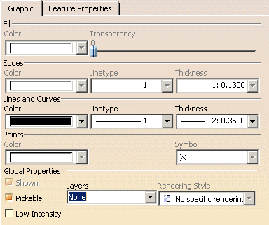
-
Select a 2D element on the CATDrawing you opened.
-
Select Edit > Properties and click the Graphic tab.
You can also right click the 2D element and then select Properties from the displayed contextual menu.
-
If needed, click the More button.
-
If needed, modify the available properties. Depending on the element you selected, not all properties will be available.
- Fill:
- you can color the selected element and set the filling transparency.
- Edges:
- you can define the color, linetype (dotted, dashed, etc.) and thickness that will be used for edges. See Graphic Properties Toolbar.
- Lines and Curves:
- you can define the color, linetype (dotted, dashed, etc.) and thickness that will be used for lines and curves. See Graphic Properties Toolbar.
- Points:
- you can define the color and the symbol that will be used for points.
- Global Properties:
- you can choose if the element will be shown or not (check/uncheck Shown option)
- you can activate or deactivate Pickable mode. If you uncheck it, geometry will not be selectable anymore. See Pick/No Pick mode.
- you can choose to display the selected element using a lower intensity. Refer to Displaying and Editing Graphic Properties (step 19) in the Infrastructure User's Guide.
- you can choose a layer for the selected geometry.
- you can select the Rendering Style (Transparent, Wireframe, Shading or Shading with edges) you want to apply to the selected element, provided that this element supports rendering styles. Refer to Displaying and Editing Graphic Properties (step 20) in the Infrastructure User's Guide.
For example, if you change the color of a table frame, the font color of the table's text will also be changed. In this case, a workaround is to change the font color after having edited the graphic properties.
-
Click OK.
For more information on graphic properties, refer to the Infrastructure User's guide.
Pick/No Pick mode
When you create elements using the No Pick mode (Pickable option unchecked),
- If you want to make one or several elements pickable back again, perform as follows:
Select Edit > Search from the menu bar and select the element(s) to be modified from the Search dialog box.
Select Edit > Properties > from the menu bar and check the Pickable option from the Properties dialog box.
- If you want to make all the elements on a sheet or in a view pickable back again, perform as follows:
Click the sheet or the view(s) to be applied the Pick mode from the specification tree.
Select Force Pick Mode from the contextual menu.
Graphic Properties Toolbar
You can also modify graphic properties using the Graphic Properties toolbar.

- the line color
- the line thickness
- the linetype
- the symbol to be used for points
- a layer for the selected geometry
- copying objects (Copy Object Format icon
 )
) - the pattern (Pattern icon
 ). This option
display the Pattern Chooser dialog box, from which you can select a
pattern.
When you turn this red thick line into a construction line (from the contextual menu: Object.Line > Definition..., Construction element option in the Line Definition dialog box), the line will become a dotted gray line. Even though you then decide to make it a standard line back again (by un-checking the Construction line option), the line will have lost its "red" and "thickness" attributes and will be assigned its original attributes.
![]()
