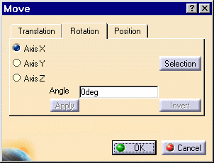
The Move dialog box is displayed. Translation options are available. To find out how to translate components, refer to Translating Components.
-
Click the Rotation tab.
-
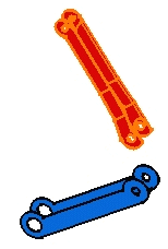
Select the component you wish to rotate, that is CRIC_BRANCH_1.
Entering a Rotation Angle
-
For example, check the Axis Y option to specify the axis of rotation.
-
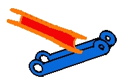
Enter 90 as the angle value in the Angle field.
The selected component is rotated accordingly.
-
Click OK to close the dialog box.
-
Repeat steps 1, 2 and 3.
Selecting Geometry to Define the Axis of Rotation
-
Click the Selection button to define a new rotation with respect to a geometrical element.
-
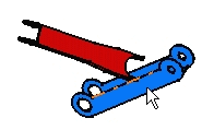
Select the edge as shown to specify the new rotation axis.
-
Enter 90 in the Angle field.
-
Click Apply to rotate the red component.
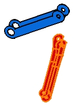
You can apply this rotation to any other components. You just need to select it and click the Apply button.
-
Click OK to exit.