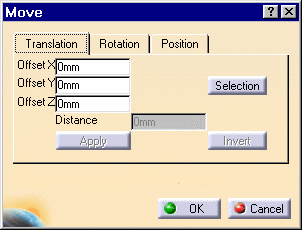
The Move dialog box is displayed. Either you specify an offset value between the element and x, y or z axis, or you select a geometric element to define the direction you need.
-
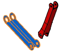
Select the component to be translated, that is CRIC_BRANCH_3.
By Entering Values
-
Enter 50 mm as the offset value, in the Offset X field. The component are translated along x axis.
-
Click Apply.
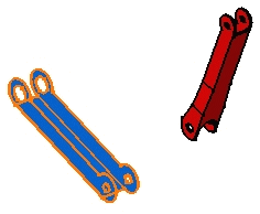
The selected component is translated accordingly.
-
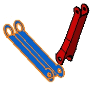
Click the Invert button to reverse the previous operation and translate the component in the opposite direction.
The component is translated in the opposite direction. You can click Apply as many times as you wish to translate the component to the desired position.
-
Click OK to close the dialog box.
-
Repeat steps 1 and 2.
By Selecting Geometric Elements
-
Click the Selection button to define a new translation with respect to a geometric element.
The Translation tab contents is grayed out. If you select a line or a plane you need to enter a distance value. The translation is then done along the selected line or normal to the selected plane. Selecting two faces or planes assumes these elements are parallel.
-
Select the red and blue faces as shown. These faces are parallel.
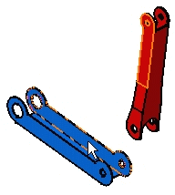
The application computes the distance between
these faces.
The Offset field then displays this distance value:
Offset X: 20mm
Offset Y: 0mm
Offset Z: 0mm
-
Click Apply to translate the blue component.
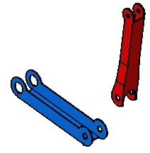
You can apply this translation to any other components. You just need to select it and click the Apply button.
-
Click OK to exit.