In order to select another element of a cylinder/cone/sphere you can:
- Specify the element to be selected using the User Selection Filter tools, see Selecting Using a Filter.
- Use the pre-selection navigator (or the keyboard arrows) for selecting the desired element, see Selecting Using the Preselection Navigator in the Infrastructure documentation.
- Publish the desired element before and select this publication, see Publishing in Assembly Design.
Make sure the list specifying the order of constraint creation is composed as follows in the Quick Constraint options:
- Surface contact
- Coincidence
- Offset
- Angle
- Parallelism
- Perpendicularity
-
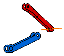
Select the axis as shown.

-
Select the axis of AXIS_BRANCH_3.
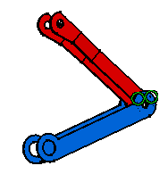
As the application cannot set a surface contact due to the type of selected elements, it creates the second optional constraint mentioned in the list, that is a coincidence constraint.

-
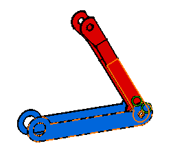
Select the faces as shown.

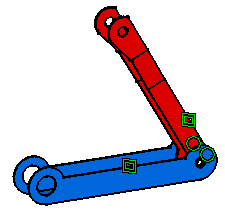
The first constraint in the list can now be set. A surface contact constraint is created.

Graphic symbols used for constraints can be customized. For more information, refer to Customizing Constraint Appearance.