-
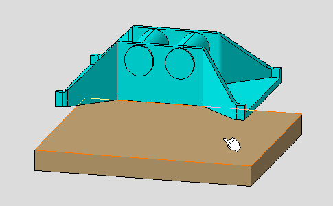
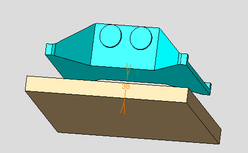
Select the face to be constrained, that is the yellow face as shown.
-
Select the second face to be constrained, that is the blue face in the direction opposite to the yellow face.
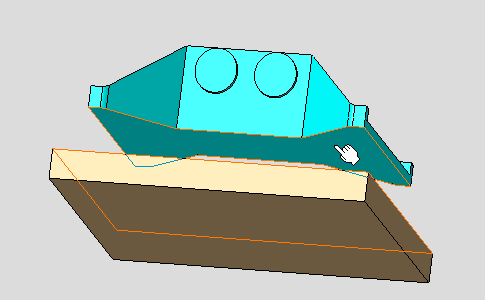
Green arrows appear on the selected faces:
-
They appear only when the orientation of the selected elements is taken into account in the offset constraint and indicate how the selected elements are designed during the assembly update.
-
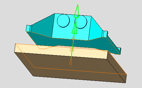
The arrow on the first selected element is the reference arrow and its orientation cannot be modified.
-
Double-click the any arrows changes the orientation of the arrow on the second selected element. See also constraint orientation in the Constraint Properties dialog box.
-
Arrow orientations are kept in the constraint and is displayed as they have been specified when editing the constraint.
The Constraint Properties dialog box appears.
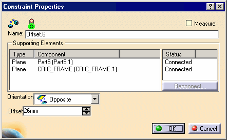
The Constraint Properties dialog box displays the constraints properties:
-
The constraint type icon:

-
The status is represented by a traffic lights icon:
-
 verified.
 -
 impossible.
 -
 not updated.
 -
 broken.
-
-
Name: the constraint name, here Offset.6
-
Measure: this mode makes the offset constraint as measure, in other words, the offset constraint is defined by the component locations, otherwise the offset constraint constrains the component locations.
-
Using the Measure mode, the offset value is displayed between brackets indicating this mode and measured from the component locations. When the offset constraint supporting elements are two non-parallel planes the offset value cannot be measured, the constraint is invalid, any value is displayed and two pound signs are displayed between the brackets (##).
-
-
Supporting Elements: the type of geometrical elements involved in the constraint, their related components, and their connection status are displayed.
-
Orientation: appear only when the orientation of the selected elements are taken into account in the coincident constraint:
-
Undefined (the application computes the best solution)
-
Same: geometrical element orientations are the same.
-
Opposite: geometrical element orientations are opposite.
-
-
Offset: the offset value.
-
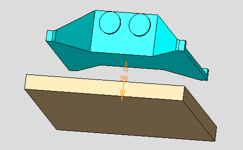
Enter 38mm in the Offset field.
Affecting a value to an offset constraint, means that the constraint drives the distance between the components.
-
Click OK to create the offset constraint.
-
Update the assembly if needed.
The offset constraint is displayed with two arrows and its offset value. This constraint is added to the specification tree too.
Graphic symbols used for constraints can be customized. For more information, refer to Constraint Creation.