The offset value is always displayed next to the offset constraint.
| |
Point | Line | Plane |
| Point |
|
|
|
| Line |
|
|
|
| Plane |
|
|
|
- NA: Not Applicable.
- Point: a point, a sphere center, a cone vertex for example.
- Line: a line, a cylinder axis, a cone axis for example.
- Plane: a plane or a planar surface for example.
Positive and Negative Offsets
- At least one of the components to be constrained must be a planar element, otherwise you cannot set positive nor negative offset values.
- The vector normal to the planar element indicates the positive offset value.
- If the planar element is an oriented plane, the normal vector pointing to the side opposite to material indicates the positive value.
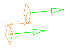
- If the planar element is a wireframe plane, the application automatically deduces the positive or negative value. Green arrows show the positive value.

-
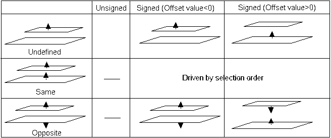
If both components are planar elements, the selection order of the elements affects the result when using the orientation option (Same, Opposite, Undefined). The normal to the first selected element gives the positive value.
