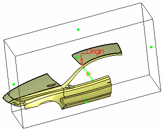
Open the Mask1.CATPart document.
-
Click Mask
 .
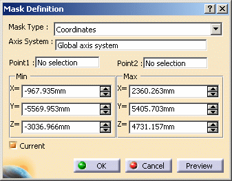
.The Mask Definition dialog box appears. -
Select the Mask Type:
Coordinates
Selecting Points
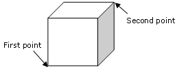
- Select a first point.
- Select a second point.
The 3D box appears, it has no manipulators. 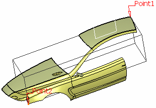
Minimum and maximum coordinates are displayed and the fields are grayed. 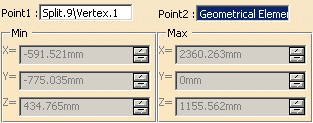
Defining Coordinates
- Key in the minimum and maximum coordinates of the box.
The 3D box appears along with manipulators. 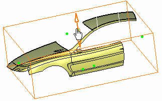
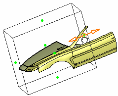
- Use the manipulators to translate each face of the box along the
current axis direction and resize the mask box.
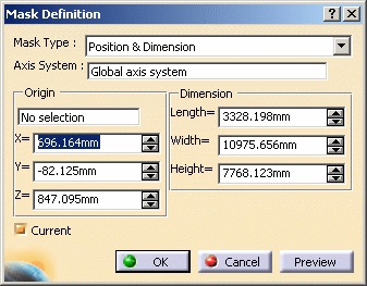
Position & Dimension
Selecting a Point
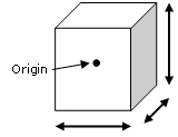
- Select a point as the origin of the box or use the contextual menu to
create a new one.
The point's coordinates are displayed and the fields are grayed: 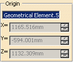
Defining Coordinates
- Key in the minimum and maximum coordinates of the point.
In both cases, the 3D box appears along with manipulators.
- Use the manipulators to translate each face of the box
along the current axis direction and resize the mask box.
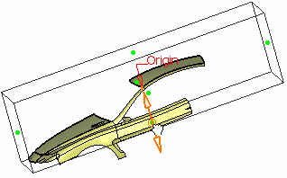
If you drag the face, the other side of the side is symmetrically moved to the other position.
-
Select the Axis System.
By default, it is automatically set to the current axis system but you can choose an another axis system or use the contextual menu to create a new one. 
The creation of the mask takes into account the size of the viewer and a depth enabling to contain the geometries displayed on the screen.
The depth of the box corresponds to the smallest dimension allowing the selection of the all elements visualized in the current view.
The mask is always oriented with the main direction of the axis system support. It is the biggest box, oriented with the axis system, that can include the geometries displayed on the screen. -
Click OK to create the mask.
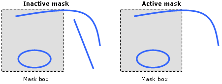
All the elements completely outside of the 3D Box are not displayed. The elements partially outside of the 3D box are displayed and the elements just on the face of the 3D box are included in the 3D box. The mask is created in the current part and is displayed under the Masks feature in the specification tree. By default, the last created mask is displayed in red in the specification tree.
Only masks that are associated with the current axis system can be activated. If the selected axis system is linked to several masks, the latter are displayed under the "Linked to current axis system" node in the specification tree.
Use the Set As Current/Set As Not Current contextual menu item on the mask feature to define the default current mask. The former active mask is inactivated.

The Set As Current/Set As Not Current contextual menu item is only available on masks located under the "Linked to current axis system" node.
Activating/Inactivating Masks
- The created mask is associated with the current axis system, but you can select another one. If you change the current axis system, the active mask becomes inactive.
- If the current axis system is the support of the created mask, you can choose to automatically activate it or not. If it is not the current one, the mask is created but inactivated.
- If there are several masks and you activate one, the former activated mask is automatically deactivated. By passing the mouse over an inactivate mask in the specification tree, it is pre-highlighted but the geometry is not displayed. If you click on the inactive mask, it is highlighted and the geometry is displayed. In both cases, the active mask remains active.
Creating Datum Masks
The icon in the specification tree looks like this:
Isolating Masks
Miscellaneous
- If you delete the active mask, all remaining masks are inactive and
all elements are displayed.
If you delete an inactive mask and an active mask exists, the latter remains active.
If you delete the axis system that is linked to several masks, the latter are automatically deleted and a warning dialog box is issued. - You can edit a mask and modify all its parameters, except for the axis system.
- In case you are working in a CATProduct
environment, and providing there are several parts, you can only see the
mask whose part is active.
Several masks can be specified in one part but there can be only one active mask in the part. If the product is active, masks cannot be applied.
- When you create a new mask in the part, you cannot select an axis system of another part. Moreover, you cannot activate a mask in an inactive part.
- The geometry that is completely outside the box is not displayed in the No Show area. However, it can still be picked from the specification tree.
- Sketches are considered as one feature.
- If all the vertices of a surface or a wire are located outside the mask box, the geometry is not displayed even if some geometry passes through the mask box.
![]()
