| Dynamic level of detail and dynamic pixel
culling allow you to modify more quickly the values set in the
Performance tab. However, bear in mind that the values you define here apply only to your current Version 5 session, contrary to the values defined via the Performance tab which are stored in your settings files and thus, are kept from one session to another unless they are explicitly modified. |
However, note that if the Level of detail or the Pixel culling option has been locked by your administrator in the Performance tab, you cannot define dynamically the level of detail or the pixel culling because the corresponding command (Define Dynamic Level of Detail or Dynamic Pixel Culling) is grayed out.
- LODs are used in a product context in Visualization mode: as a consequence, you must activate the cache for your LOD settings to be taken into account (select the Work with the cache system check box in Tools > Options > Infrastructure > Product Structure > Cache Management)
- select the Save level of details in cgr check box in the Cgr Management tab.
- activate at least the Triangles mode in the View Mode Customization dialog box.
-
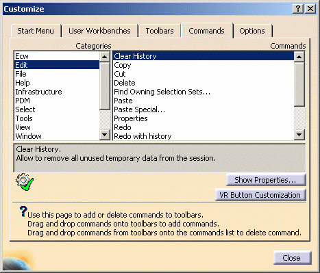
Select Tools > Customize.
-
Click the Commands tab to list the commands available.
-
Select the category All Commands that lists all commands available for the workshop you are working in as well as global commands (e.g. Open, Save, etc.):

-
Select Define Dynamic Level of Detail from the command list.
-
Drag the command from the command list to the toolbar of your choice to add the command.
-
Drop the command onto the desired toolbar.
Note that some toolbars (such as the View toolbar) cannot be customized. As a consequence, you cannot drag and drop commands onto them. For more information, refer to Customizing a Toolbar by Dragging and Dropping. -
Repeat steps 5 and 6 to drag and drop the Define Dynamic Pixel Culling command.
In our example, the two commands have been added to the Standard toolbar: 
These commands are identified by two different icons: -
 identifies Define Dynamic Pixel Culling
 -
 identifies Define Dynamic Level of Detail.
-
-
Set your own values either by entering them directly in the corresponding box or use the arrows increase or decrease the value:
-
for pixel culling, you can enter a value comprised between 0 and 40. The higher the value, the more quickly you can move large parts
-
for level of detail, you can also enter a value comprised between 0 and 40. The higher the value, the lower the level of detail.
-
-
Perform a viewing operation, for instance pan or rotate your model.
You can see that your new values have been taken into account.
![]()