 |
| This task shows you how to customize Product Structure
settings, that are divided in five sections:
|
Part Number
|
Defining the Default Part Number of
the Component to be Imported
 |
By default, this option is not selected. |
Check Manual input if you wish to assign the name you wish
to the component you insert into the assembly.
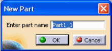
Note
that this panel is not displayed by the "New From" command since a
precise copy must be produced and therefore no modification, like adding
a geometrical set or an ordered geometrical set, should be performed.
The
panel can be displayed by selecting the Manual Input setting. This will
enable to modify the part name generated by the New FROM command. |
Low Light Mode
|
Selecting the Low Light Mode of the component that does
not belong to the active level
 |
By default, this option is not selected. |
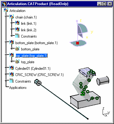
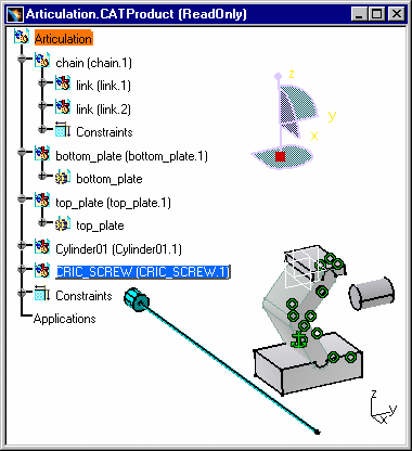
If you check the Low Light Mode option and select
(double-click) a component in a CATProduct, it becomes UI Active
(highlighted) in the Geometry Space:
|
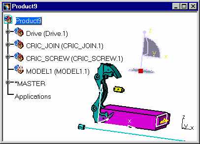
| The second example shows that the operation is also
possible with Models.
This is a visualization mode : the selected element remains highlighted
and the other geometric components are in low light (gray-colored). If you
double-click on another element, it immediately becomes highlighted and
the other ones are dimmed. |
Model in BOM
|
Describing the model file in the Bill Of Material
 |
By default, this option is not selected. |
|
Select the Model In BOM option in order to have
access the Models' information (path name for instance) in the document's
BOM.
-
Open a CATIA document containing one or several models.
-
Select the Analyze -> Bill Of Material Menu
and click the Listing Report tab.
-
Click on the Refresh button in order to
access to the components' properties (path name for example):
These Models have been inserted into a CATProduct and you
can now visualize the Models' path name. You can find the original
directories in which the models were stored. When there is a broken link,
you can read the following expression : "Unretrieved document". |
Reframe mode after insert existing component
|
Reframe Mode after insert existing component
 |
By default, this option is selected. |
Check the Reframe Mode options you need.
In the following examples, Global reframe has been selected.
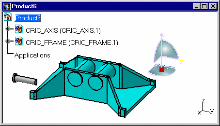
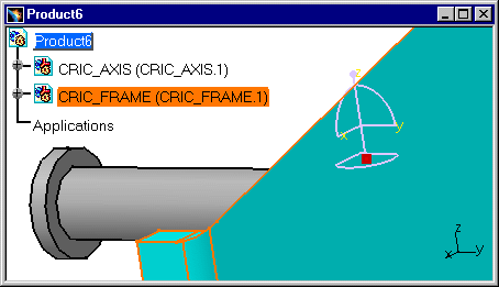
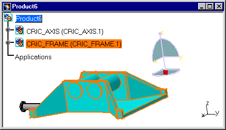
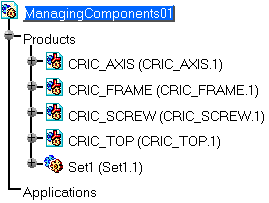
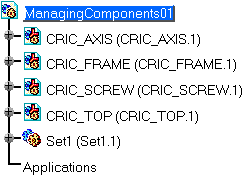
CRIC_FRAME.1 has been inserted into Product6 and a different Reframe Mode
has been selected beforehand. The original CATProduct looks like this:
|
- Global Reframe: this is the default value, Global Reframe zooms on
the whole geometry and it allows you to see all the components. After
the insertion of CRIC_FRAME.1 into Product6, the visualization of the
geometry is re-adjusted in CATIA window so that all the components can
be seen.
- No Reframe: if you insert an element in the product, you may not see
the totality of this element in the CATIA window. The visualization on
the already existing component, CRIC_AXIS.1, does not change. There is
no Reframe on the last inserted element.
- Reframe on last inserted component: This zoom-in capability improves
the visualization of the last inserted component. Therefore, in some
cases, you cannot visualize the other CATIA objects because there is an
automatic Reframe on the last inserted component.
|
Specification Tree
|
 |
Customizing the Specification Tree
 |
By default, this option is not selected. |
|
| |
 |
To display the Constraints, Parameters and Relations,
you need go to the Tree Customization tab.
To modify the setting Automatic expand, you need to select the
Tools->Options->General->Display category and the Tree
Manipulation tab:
|

