|
|
This task illustrates how to create then
locally modify a Multi-Axis Flank Contouring operation in the
program. First the operation will be globally created in
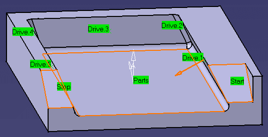
Tanto Fan mode. Then the first
and last drives will be locally modified to:
|
||
|
|
Open the
Part5XDemoGFC.CATPart
document, then select Machining > Advanced Machining from
the Start menu. Make the Manufacturing Program current in the
specification tree. |
||
|
|
1. | Select the Multi-Axis Flank Contouring icon
|
|
| 2. | Use the sensitive icon in the Geometry page
|
||
|
|
|||
| 3. | Select the
Strategy tab page
The other Strategy parameters can be left at the default values. The default Tool, Feeds and Speeds, and NC macros can also be used. |
||
| 4. | Check the validity of the operation by replaying the tool path. | ||
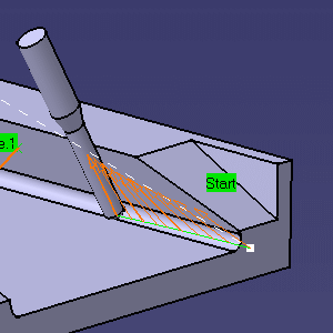 |
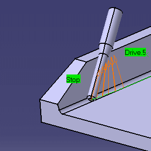 |
||
| 5. | Right click the drive surfaces area in the sensitive icon
of the Geometry page and select
Local Modifications. The Local Drive Surfaces dialog box
appears:
|
||
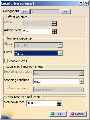
| 6. | Double click line 1, which corresponds to the first
drive. The Local Drive Surface 1 dialog box appears. Modify the drive by adding a 2mm offset and changing the tool axis guidance to Tanto. Click OK.
The updated Local Drives dialog box appears:
|
||
| 7. | Double click line 5, which corresponds to the last drive, and modify it in the same way. | ||
| 8. | Check the validity of the modifications by replaying the tool path. Tanto replaces Tanto Fan on first and last drives. | ||
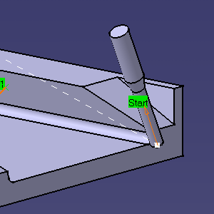 |
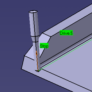 |
||
| 9. |
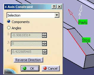
Click the 4-axis constraint symbol (Optional 4X plane) on the
Strategy tab page
|
||
| 10. |
In
the Local Drive 1 and Local Drive 5 dialog boxes, select the Enable
4-axis checkbox.
The Local Drives dialog box is updated:
|
||
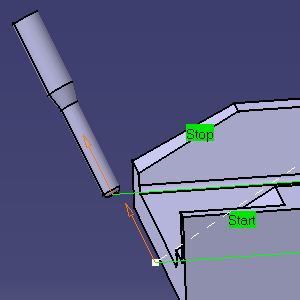
| 11. | Check the validity of the modifications by replaying the tool path. The 4-axis constraint is applied on the first and last drives. | ||
|
|
|||
| 12. | Double click line 3:
the Local Drive Surface 3 dialog box appears. Modify the local slowdown rate to 90%. Click OK. The Local Drives dialog box is updated:
|
||
| 13. | Check the validity of the modification by
replaying the tool path. The feedrate reduction
is applied is applied on the third drive. Note that the
local reduction can be combined with the Feedrate reduction in corners
settings in the Feeds and Speeds
tab page |
||
| 14. | Click OK to create the operation. | ||
|
|
Please note:
|
||
|
|
|||

