The following basic and constructed data types are defined in the eXternal Data Representation (XDR) standard:
A general paradigm declaration is shown for each type. The < and > (angle brackets) denote variable-length sequences of data, while the [ and ] (square brackets) denote fixed-length sequences of data. The letters n, m, and r denote integers. See the Using an XDR Data Description Example for an extensive example of the data types.
XDR defines two integer data types. The first type is signed and unsigned integers. The second type is signed and unsigned hyperintegers.
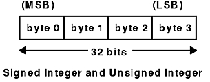
The XDR standard defines signed integers as integer. A signed integer is a 32-bit datum that encodes an integer in the range [-2147483648 to 2147483647]. The signed integer is represented in twos complement notation. The most significant byte is 0 and the least significant is 3.
An unsigned integer is a 32-bit datum that encodes a nonnegative integer in the range [0 to 4294967295]. The unsigned integer is represented by an unsigned binary number whose most significant byte is 0; the least significant is 3. See the Signed Integer and Unsigned Integer figure.
Figure 4-2. Signed Integer and Unsigned Integer. This diagram shows the most significant byte on the left, which is byte 0. To the right of byte 0, is byte 1, followed by byte 2, and then byte 3 (the least significant byte). The length of the 4 bytes is 32 bits.

The XDR standard also defines 64-bit (8-byte) numbers called signed and unsigned hyperinteger. Their representations are extensions of signed integers and unsigned integers. Hyperintegers are represented in twos complement notation. The most significant byte is 0 and the least significant is 7. See the Signed Hyperinteger and Unsigned Hyperinteger figure.
Figure 4-3. Signed Hyperinteger and Unsigned Hyperinteger. This diagram shows the most significant byte on the left which is byte 0. To the right of byte 0, is byte 1, followed by byte 2, and byte 3 continued up to byte 7 (the least significant byte). The length of the 8 bytes is 64 bits.

The XDR standard provides enumerations for describing subsets of integers. XDR defines enumerations as enum. Enumerations have the same representation as signed integers and are declared as follows:
enum { name-identifier = constant, ... } identifier;
Encoding any integers as enum, besides those assigned in the enum declaration, causes an error condition.
Booleans occur frequently enough to warrant an explicit data type in the XDR standard.
Booleans are declared as follows:
bool identifier;
This declaration is equivalent to:
enum { FALSE = 0, TRUE = 1 } identifier;
The XDR standard defines two floating-point data types: single-precision and double-precision floating points.
XDR defines the single-precision floating-point data type as a float. The length of a float is 32 bits, or 4 bytes. Floats are encoded using the IEEE standard for normalized single-precision floating-point numbers.
The single-precision floating-point number is declared as follows:
(-1)**S * 2**(E-Bias) * 1.F
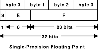
See the Single-Precision Floating-Point figure.
Figure 4-4. Single-Precision Floating-Point. The first line of this diagram lists bytes 0 through 3, with the most significant byte 0 first, and the least significant byte 3 last. The second line of the diagram shows the corresponding fields and their respective lengths: S (1 bit) and E (8 bits) extend under byte 0 and byte 1, while F (23 bits) extends from byte 1 to byte 3. The third line shows the total length of bytes 0 through 3, which is 32 bits.

The most and least significant bytes of an integer are 0 and 3. The most and least significant bits of a single-precision floating-point number are 0 and 31. The beginning (and most significant) bit offsets of S, E, and F are 0, 1, and 9, respectively. These numbers refer to the mathematical positions of the bits but not to their physical locations, which vary from medium to medium.
The IEEE specifications should be considered when encoding signed zero, signed infinity (overflow), and denormalized numbers (underflow). According to IEEE specifications, the NaN (not-a-number) is system-dependent and should not be used externally.
The XDR standard defines the encoding for the double-precision floating-point data type as a double. The length of a double is 64 bits or 8 bytes. Doubles are encoded using the IEEE standard for normalized double-precision floating-point numbers.
The double-precision floating-point data type is declared as follows:
(-1)**S * 2**(E-Bias) * 1.F
See the Double-Precision Floating Point figure.
Figure 4-5. Double-Precision Floating-Point. The first line of this diagram lists bytes 0 through 7. The second line of the diagram shows the corresponding fields and their respective lengths: S (1 bit) and E (11 bits) extend under byte 0 through byte 2, while F (52 bits) extends from byte 3 to byte 7. The third line shows the total length of bytes 0 through 7, which is 64 bits.

The most and least significant bytes of a number are 0 and 3. The most and least significant bits of a double-precision floating-point number are 0 and 63. The beginning (and most significant) bit offsets of S, E, and F are 0, 1, and 12, respectively. These numbers refer to the mathematical positions of the bits but not to their physical locations, which vary from medium to medium.
The IEEE specifications should be consulted when encoding signed zero, signed infinity (overflow), and denormalized numbers (underflow). According to IEEE specifications, the NaN (not-a-number) is system-dependent and should not be used externally.
The XDR standard defines two types of opaque data: fixed-length and variable-length opaque data.
XDR defines fixed-length uninterpreted data as opaque. Fixed-length opaque data is declared as follows:
opaque identifier[n];
The constant n is the static number of bytes necessary to contain the opaque data. If n is not a multiple of 4, then the n bytes are followed by enough (0 to 3) residual 0 bytes, r, to make the total byte count of the opaque object a multiple of 4. See the Fixed-Length Opaque figure.
Figure 4-6. Fixed-Length Opaque. This diagram contains 4 lines of information. The second line of the diagram is the main line, listing bytes as follows: byte 0, byte 1, dots signifying the bytes between byte 1 and byte n-1. The next byte is labeled: byte n-1, and is followed by residual byte 0. Dots signify more residual bytes that end in a final byte 0. The remaining lines of the diagram describe this main line of bytes. The first line assigns numbers to the bytes as follows: number 0 for byte 0, number 1 for byte 1, and dots signifying a continuing sequence. The third line assigns byte values to the bytes in the main line as follows: byte 0 through byte n-1 yield n bytes. All the residual bytes together equal r bytes. The fourth line, which spans the entire diagram, shows the following equation:n+r (where (n+r) mod 4 = 0).

XDR also defines variable-length uninterpreted data as opaque. Variable-length (counted) opaque data is defined as a sequence of n arbitrary bytes, numbered 0 through n-1. Opaque data is encoded as an unsigned integer and followed by the n bytes of the sequence.
Byte m of the sequence always precedes byte m+1, and byte 0 of the sequence always follows the sequence length (count). Enough (0 to 3) residual 0 bytes, r, are added to make the total byte count a multiple of 4.
Variable-length opaque data is declared in one of the following forms:
opaque identifier<m>;
opaque identifier<>;
The constant m denotes an upper bound for the number of bytes that the sequence can contain. If m is not specified, as in the second declaration, it is assumed to be (2**32) - 1, which is the maximum length. The constant m would normally be found in a protocol specification. See the Variable-Length Opaque figure.
Figure 4-7. Variable-Length Opaque. This diagram contains 4 lines of information. The second line of the diagram is the main line, listing segments as follows: length n, byte 0, byte 1, and then dots signifying the bytes between byte 1 and byte n-1. The next byte is labeled:n-1, followed by residual byte 0. Dots signify more residual bytes that end in a final byte 0. The remaining lines of the diagram describe this main line. The first line assigns numbers as follows: numbers 0 through 3 for length n, number 4 for byte 0, number 5 for byte 1, and dots signifying a continuing sequence. The third line assigns byte values to the main line as follows: length n is 4 bytes, byte 0 through byte n-1 yield n bytes. All the residual bytes together equal r bytes. The fourth line, which spans the entire diagram, shows the following equation:n+r (where (n+r) mod 4 = 0).

Note: Encoding a length n that is greater than the maximum described in the protocol specification causes an error.
The XDR standard defines two type of arrays: fixed-length and variable-length.
Fixed-length arrays of homogeneous elements are declared as follows:
type-name identifier[n];
Fixed-length arrays of elements are encoded by individually coding the elements of the array in their natural order, 0 through n-1. Each element size is a multiple of 4 bytes. Although the elements are of the same type, they may have different sizes. For example, in a fixed-length array of strings, all elements are of the string type, yet each element varies in length. See the Fixed-Length Array figure.
Figure 4-8. Fixed-Length Array. This diagram shows from the left, element 0, element 1, a series of dots to signify the elements between element 1 and element n-1. The length is equal to n elements.

The XDR standard provides counted byte arrays for encoding variable-length arrays of homogeneous elements. The array is encoded as the element count n (an unsigned integer) followed by the encoding of each of the array's elements, starting with element 0 and progressing through element n-1.
Variable-length arrays are declared as follows:
type-name identifier<m>;
type-name identifier<>;
The constant m specifies the maximum acceptable element count of an array. If m is not specified, it is assumed to be (2**32) - 1. See the Variable-Length Array figure.
Figure 4-9. Variable-Length Array. This diagram contains 3 lines of information. The second line of the diagram is the main line, listing the following: n, element 0, element 1, and a series of dots to signify a continuing sequence ending in element n-1. The first line of the diagram contains the numbers 0 through 4, with 0 on the first border of n and 4 on the shared border of n an element 0. The third line assigns values to parts of the main line as follows: n equals 4 bytes, and element 0 through element n-1 equal n elements.

Note: Encoding a length n greater than the maximum described in the protocol specification causes an error.
The XDR standard defines a string of n (numbered 0 through n-1) ASCII bytes to be the number n encoded as an unsigned integer and followed by the n bytes of the string. Byte m of the string always precedes byte m+1, and byte 0 of the string always follows the string length. If n is not a multiple of 4, then the n bytes are followed by enough (0 to 3) residual zero bytes, r, to make the total byte count a multiple of 4.
Counted byte strings are declared as one of the following:
string object<m>;
string object<>;
The constant m denotes an upper bound of the number of bytes that a string may contain. If m is not specified, as in the second declaration, it is assumed to be (2**32) - 1, which is the maximum length. The constant m would normally be found in a protocol specification. For example, a filing protocol may state that a file name can be no longer than 255 bytes, as follows:
string filename<255>;
See the Counted Byte String figure.
Figure 4-10. Counted Byte String. This diagram contains 4 lines of information. The second line of the diagram is the main line, listing as follows: length n, byte 0, byte 1, dots signifying the bytes between byte 1 and byte n-1. The next byte is labeled:n-1, followed by residual byte 0. Dots signify more residual bytes that end in a final byte 0. The remaining lines of the diagram describe this main line. The first line assigns numbers as follows: numbers 0 through 3 for length n, number 4 for byte 0, number 5 for byte 1, and dots signifying a continuing sequence. The third line assigns byte values to the main line as follows: length n is 4 bytes, byte 0 through byte n-1 equal n bytes. All the residual bytes together equal r bytes. The fourth line, which spans the entire diagram, shows the following equation:n+r (where (n+r) mod 4 = 0).

Note: Encoding a length n greater than the maximum described in the protocol specification causes an error.
Using the primitive routines, the programmer can write unique XDR routines to describe arbitrary data structures such as elements of arrays, arms of unions, or objects pointed to from other structures. The structures themselves may contain arrays of arbitrary elements or pointers to other structures.
Structures are declared as follows:
struct {
    component-declaration-A;
    component-declaration-B;
    ...
} identifier;
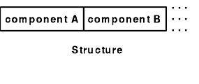
In a structure, the components are encoded in the order of their declaration in the structure. Each component size is a multiple of four bytes, although the components may have different sizes. See the Structure figure.
Figure 4-11. Structure. This diagram shows a line of components side by side as follows: component A, component B, and dots signifying a continuing sequence.

A discriminated union is a union data structure that holds various objects, with one of the objects identified directly by a discriminant. The discriminant is the first item to be serialized or deserialized. A discriminated union includes both a discriminant and a component. The type of discriminant is either integer, unsigned integer, or an enumerated type, such as bool. The component is selected from a set of types that are prearranged according to the value of the discriminant. The component types are called arms of the union. The arms of a discriminated union are preceded by the value of the discriminant that implies their encoding. See the Using XDR Discriminated Union Example.
Discriminated unions are declared as follows:
union switch (discriminant-declaration) {
    case discriminant-value-A:
    arm-declaration-A;
    case discriminant-value-B:
    arm-declaration-B;
    ...
    default: default-declaration;
} identifier;
Each case keyword is followed by a legal value of the discriminant. The default arm is optional. If an arm is not specified, a valid encoding of the union cannot take on unspecified discriminant values. The size of the implied arm is always a multiple of four bytes.
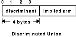
The discriminated union is encoded as the discriminant, followed by the encoding of the implied arm.
See the following figure of a discriminated union.
Figure 4-12. Discriminated Union. This diagram shows a discriminant (which is 4 bytes) and an implied arm side by side.

An XDR void is a zero-byte quantity. Voids are used for describing operations that take no data as input or output. Voids are also useful in unions, where some arms contain data and others do not.
The declaration for a void follows:
void;
Voids are illustrated as follows:
 ++
   | |
 ++
 --><-- 0 bytes
A constant is used to define a symbolic name for a constant, and it does not declare any data. The symbolic constant can be used anywhere a regular constant is used.
The data declaration for a constant follows this form:
const name-identifier = n;
The following example defines a symbolic constant, DOZEN, that is equal to 12:
const DOZEN = 12;
A type definition (a typedef statement) does not declare any data, but serves to define new identifiers for declaring data.
The syntax for a type definition is:
typedef declaration;
The new type name is the variable name in the declaration part of the type definition. For example, the following defines a new type called eggbox, using an existing type called egg:
typedef egg eggbox[DOZEN];
Variables declared using the new type name are equivalent to variables declared using the existing type. For example, the following two declarations for the variable fresheggs are equivalent:
eggbox fresheggs;
egg    fresheggs[DOZEN];
A type definition can also have the following form:
typedef <<struct, union, or enum definition>> identifier;
An alternative type definition form is preferred for structures, unions, and enumerations. The type definition form can be converted to the alternative form by removing the typedef keyword and placing the identifier after the struct, union, or enum keyword, instead of at the end. For example, here are the two ways to define the type bool:
enum bool {       /*  preferred alternative  */
FALSE = 0,
TRUE = 1
};
typedef enum {F=0, T=1} bool;
The first syntax is preferred because the programmer does not have to wait until the end of a declaration to determine the name of the new type.
Optional data is a type of union that occurs so frequently it has its own syntax. The optional data type is closely coordinated to the representation of recursive data structures by the use of pointers in high-level languages, such as C or Pascal. The syntax for pointers is the same as that for C language.
The syntax for optional data is as follows:
type-name *identifier;
The declaration for optional data is equivalent to the following union:
union switch (bool opted) {
    case TRUE:
    type-name element;
    case FALSE:
    void;
} identifier;
Because bool opted can be interpreted as the length of the array, the declaration for optional data is also equivalent to the following variable-length array declaration:
type-name identifier<1>;
Optional data is very useful for describing recursive data structures such as linked lists and trees. For example, the following defines a stringlist type that encodes lists of arbitrary length strings:
struct *stringlist {
    string item<>;
    stringlist next;
};
The example can be equivalently declared as a union, as follows:
union stringlist switch (bool opted) {
    case TRUE:
        struct {
            string item<>;
            stringlist next;
        } element;
    case FALSE:
        void;
};
The example can also be declared as a variable-length array, as follows:
struct stringlist<1> {
    string item<>;
    stringlist next;
};
Because both the union and the array declarations obscure the intention of the stringlist type, the optional data declaration is preferred.