The topics discussed in this section are:
The network adapter card is the hardware that is physically attached to the network cabling. It is responsible for receiving and transmitting data at the physical level. The network adapter card is controlled by the network adapter device driver.
A machine must have one network adapter card (or connection) for each network (not network type) to which it connects. For instance, if a host attaches to two token-ring networks, it must have two network adapter cards.
TCP/IP uses the following network adapter cards and connections:
The Ethernet and 802.3 network technologies use the same type of adapter.
Each machine provides a limited number of expansion slots, some or all of which you might wish to use for communications adapters. Additionally, each machine supports a limited number of communications adapters of a given type. Each machine supports up to eight Ethernet/802.3 adapters, up to eight token-ring adapters, and one asynchronous adapter card with up to 64 connections. Within these limits (software limitations), you can install any combination of these adapters up to the total number of expansion slots available in your machine (hardware limitations).
Only one Transmission Control Protocol/Internet Protocol (TCP/IP) interface is configurable regardless of the number of Serial Optical Channel Converters supported by the system. The Serial Optical device driver makes use of both channel converters even though only one logical TCP/IP interface is configured.
To configure and manage token-ring
or Ethernet adapters, use the tasks in the following table.
| Configuring and Managing Adapters Tasks | |||
|---|---|---|---|
| Task | SMIT Fast Path | Command or File | Web-based System Manager Management Environment5 |
| Configure an Adapter | smit chgtok (token ring)
smit chgenet (Ethernet) |
|
|
| Determining a Network Adapter Hardware Address | smit chgtok (token ring)
smit chgenet (Ethernet) | lscfg -l tok0 -v (token ring)2
lscfg -l ent0 -v (Ethernet)2 |
|
| Setting an Alternate Hardware Address | smit chgtok (token ring)
smit chgenet (Ethernet) |
|
|
Notes:
- The name of a network adapter can change if you move it from one slot to another or remove it from the system. If you ever move the adapter, issue the diag -a command to update the configuration database.
- Substitute your adapter name for tok0 and ent0.
- Substitute your hardware address for 0X10005A4F1B7F.
- After performing this procedure, you might experience a disruption of communication with other hosts until they flush their Address Resolution Protocol (ARP) cache and obtain the new hardware address of this host.
- These tasks are not available in Web-based System Manager Management Environment.
VLANs (Virtual Local Area Networks) can be thought of as logical broadcast domains. A VLAN splits up groups of network users on a real physical network onto segments of logical networks. This implementation supports the IEEE 802.1Q VLAN tagging standard with the capability to support multiple VLAN IDs running on Ethernet adapters. Each VLAN ID is associated with a separate Ethernet interface to the upper layers (IP, etc.) and creates unique logical Ethernet adapter instances per VLAN, for example ent1, ent2 and so on.
The IEEE 802.1Q VLAN support can be configured over any supported Ethernet adapters. The adapters must be connected to a switch that supports IEEE 802.1Q VLAN.
You can configure multiple VLAN logical devices on a single system. Each VLAN logical devices constitutes an additional Ethernet adapter instance. These logical devices can be used to configure the same Ethernet IP interfaces as are used with physical Ethernet adapters. As such, the no option, ifsize (default 8), needs to be increased to include not only the Ethernet interfaces for each adapter, but also any VLAN logical devices that are configured. See the no command documentation.
Each VLAN can have a different maximum transmission unit (MTU) value even if sharing a single physical Ethernet adapter.
VLAN support is managed through SMIT. Type the smit vlan fast path from the command line and make your selection from the main VLAN menu. Online help is available.
After you configure VLAN, configure the IP interface, for example, en1 for standard Ethernet or et1 for IEEE 802.3, using Web-based System Manager, SMIT, or commands.
Notes:
- If you try to configure a VLAN ID value that is already in use for the specified adapter, the configuration fails with the following error:
Method error (/usr/lib/methods/chgvlan): 0514-018 The values specified for the following attributes are not valid: vlan_tag_id VLAN Tag ID- If a user (for example, IP interface) is currently using the VLAN logical device, any attempt to remove the VLAN logical device fails. A message similar to the following displays:
Method error (/usr/lib/methods/ucfgcommo):
        0514-062 Cannot perform the requested function because the
                 specified device is busy.
To remove the logical VLAN device, first detach the user. For example, if the user is IP interface en1, then you can use the following command:
ifconfig en1 detachThen remove the network interface using the SMIT TCP/IP menus.
- If a user (for example, IP interface) is currently using the VLAN logical device, any attempt to change the VLAN characteristic (VLAN tag ID or base adapter) fails. A message similar to the following displays:
Method error (/usr/lib/methods/chgvlan):
        0514-062 Cannot perform the requested function because the
                 specified device is busy.
To change the logical VLAN device, first detach the user. For example, if the user is the IP interface en1, you could use the following command:
ifconfig en1 detachThen change the VLAN and add the network interface again using the SMIT TCP/IP menus.
tcpdump and trace can be used to troubleshoot the
VLAN. The trace hook ID for each type of transmit packet follows:
| transmit packets | 3FD |
| receive packets | 3FE |
| other events | 3FF |
The entstat command gives the aggregate statistics of the physical adapter for which the VLAN is configured. It does not provide the individual statistics for that particular VLAN logical device.
Remote dump is not supported over a VLAN. Also, VLAN logical devices cannot be used to create a Cisco Systems' Etherchannel.
Asynchronous Transfer Mode (ATM) is an international standard that defines a high-speed networking method to transport any mixture of voice, video, and traditional computer data across local, municipal, and wide-area networks (LANs, MANs, and WANs). ATM adapters provide full-duplex connectivity for RS/6000 servers or clients using permanent virtual circuits (PVCs) and switched virtual circuits (SVCs). The PVC and SVC implementations are designed to be compliant with the ATM Forum specifications. The maximum number of virtual circuits supported depends on the adapter. Most adapters support at least 1024 virtual circuits.
Asynchronous Transfer Mode (ATM) is a cell-switching, connection-oriented technology. In ATM networks, end stations attach to the network using dedicated full duplex connections. The ATM networks are constructed using switches, and switches are interconnected using dedicated physical connections. Before any data transfers can begin, end-to-end connections must be established. Multiple connections can and do exist on a single physical interface. Sending stations transmit data by segmenting Protocol Data Units (PDUs) into 53-byte cells. Payload stays in the form of cells during network transport. Receiving stations reassemble cells into PDUs. The connections are identified using a virtual path identifier (VPI) and a virtual channel identifier (VCI). The VPI field occupies one byte in the ATM cell five-byte header; whereas, the VCI field occupies two bytes in the ATM cell five-byte header. Basically, a VPI:VCI pair identifies the source of the ATM cell. The function of the ATM switch is to recognize the source of the cell, determine the next hop, and output the cell to a port. The VPI:VCI changes on a hop-by-hop basis. Thus, VPI:VCI values are not universal. Each virtual circuit is described as a concatenation of VPI:VCI values across the network.
ATM architecture has two kinds of virtual circuits: permanent (PVCs) and switched (SVCs).
The ATM address is constructed by registering with the ATM network and by acquiring the most significant 13 bytes. The next six bytes contain the adapter's factory-assigned, unique MAC address. The least significant byte is the selector. Use of this byte is left to the discretion of the end station. ATM networks do not interpret this byte.
The Internet Engineering Task Force RFC1577: Classical IP and ARP over ATM standard specifies the mechanism for implementing Internet Protocol (IP) over ATM. Since ATM is connection-oriented technology and IP is a datagram-oriented technology, mapping the IP over ATM is not trivial.
In general, the ATM network is divided into logical IP subnetworks (LISs). Each LIS is comprised of some number of ATM stations. LISs are analogous to traditional LAN segments. LISs are interconnected using routers. A particular adapter (on an ATM station) can be part of multiple LISs. This feature can be very useful for implementing routers.
RFC1577 specifies RFC1483, which specifies logical link control/Sub-Network Access Protocol (LLC/SNAP) encapsulation as the default. In PVC networks for each IP station, all PVCs must be manually defined by configuring VPI:VCI values. If LLC/SNAP encapsulation is not being used, the destination IP address associated with each VPI:VCI must be defined. If LLC/SNAP encapsulation is being used, the IP station can learn the remote IP address by an InARP mechanism.
For SVC networks, RFC1577 specifies an ARP server per LIS. The purpose of the ARP server is to resolve IP addresses into ATM addresses without using broadcasts. Each IP station is configured with the ATM address of the ARP server. IP stations set up SVCs with the ARP server, which in turn, sends InARP requests to the IP stations. Based on InARP reply, an ARP server sets up IP to ATM address maps. IP stations send ARP packets to the ARP server to resolve addresses, which returns ATM addresses. IP stations then set up a SVC to the destination station and data transfer begins. The ARP entries in IP stations and the ARP server age based on a well defined mechanism. For both the PVC and SVC environments, each IP station has at least one virtual circuit per destination address.
The Internet Engineering Task Force RFC2225 adds the support of ATM ARP Request Address list to RFC1577. The ATM ARP Request Address list is a list containing one or more ATM addresses of individual ATM ARP servers located within the LIS. The RFC2225 client eliminates the single point of failure associated with the 1577 clients' ATM ARP services. The 2225 clients have the ability to switch to backup ARP servers when the current ATM ARP server fails.
RS/6000 sets the first entry in the ATM ARP Request Address list as the Primary ATM ARP server and the rest of the entries as Secondary ATM ARP servers.
The client will always try to use the Primary ATM ARP server. If the effort to connect to the Primary ATM ARP server fails, the client tries to connect to the first Secondary server (the position in the ATM ARP Request Address list determines the order of the Secondary ATM ARP server). If the connection to the first Secondary ATM ARP server fails, the client tries to contact the next Secondary ATM ARP server in the list. This process continues until the connection is successful.
If the connection to the Primary ATM ARP server fails, regardless of which Secondary ATM ARP server it is connected to or attempting to connect to, the client continues to retry the Primary ATM ARP server every 15 minutes. If it finally connects to the Primary ATM ARP server, then the connection to the current Secondary ATM ARP server is dropped.
The ATM ARP Request Address list is entered manually either through SMIT or by using the ifconfig command. The ATM ARP Request Address list cannot be configured with the Management Information Base (MIB).
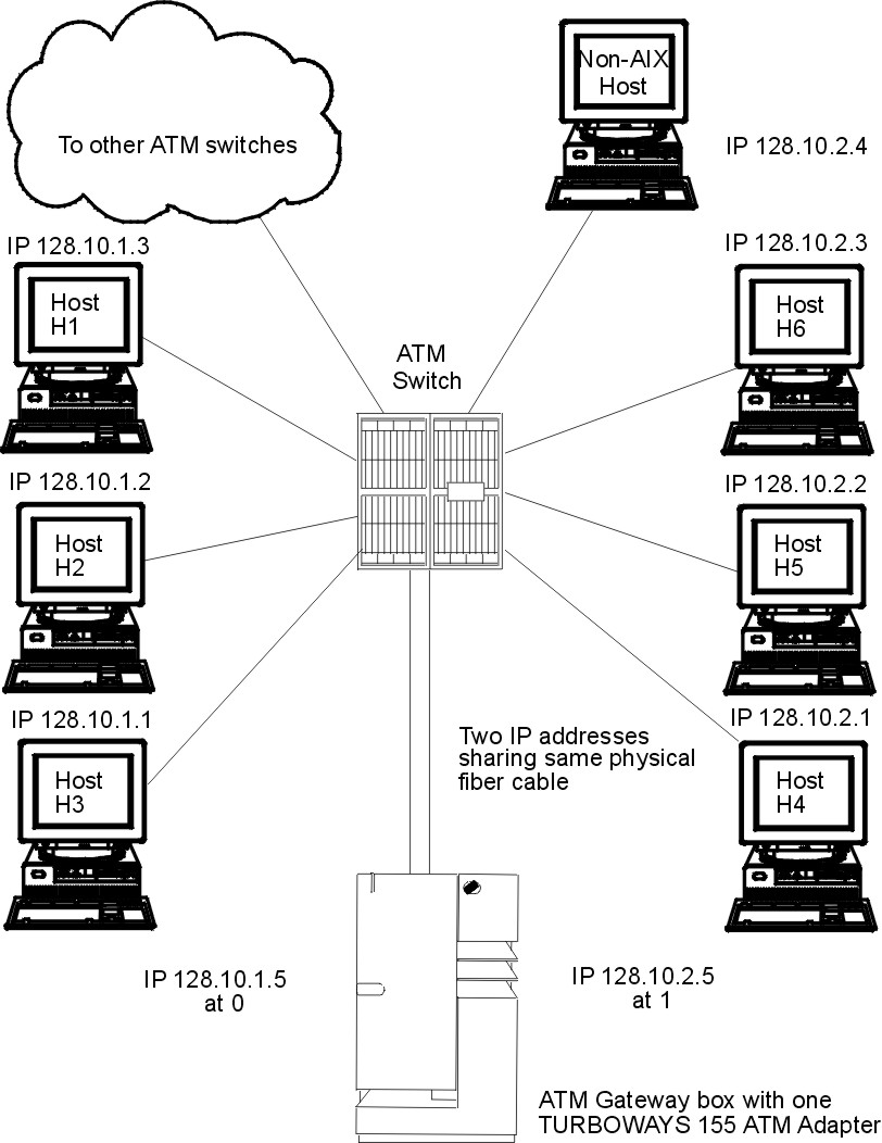
Use the "Representative ATM Network" figure as an example to configure your network.
Within the "Representative ATM Network" figure, one logical IP subnet is represented by dashed lines from each host to the switch. The other IP subnet is represented by solid lines from each host to the switch.
Figure 3-12. Representative ATM Network. This illustration depicts an ATM network laid out in a typical star topography. In the center of the star is the ATM switch. Numbered IP hosts are branched off of the switch as are links to other ATM switches and one ATM gateway box and adapter.
|
The following Representative Host
Configuration table indicates how hosts H3 and H4 are configured to
communicate with a gateway and with each host on its own logical IP
subnet.
| Representative Host Configuration | ||
| Network Interface Driver | VPI:VCI | Comment |
| Host H3 | ||
| at0 | 0:40 | Connection to 128.10.1.5 (gateway) |
| at0 | 0:42 | Connection to 128.10.1.2 |
| at0 | 0:43 | Connection to 128.10.1.3 |
| Host H4 | ||
| at0 | 0:50 | Connection to 128.10.2.5 (gateway) |
| at0 | 0:52 | Connection to 128.10.2.2 |
| at0 | 0:53 | Connection to 128.10.2.3 |
| at0 | 0:54 | Connection to 128.10.2.4 |
To reach hosts on another logical IP subnet, only a VPI:VCI connection to the gateway needs to be created. (The VPI:VCIs are for illustration purposes only.)
The ATM gateway box has one ATM with two IP addresses sharing the same physical cable.
Using the "Representative ATM Network" figure as an example, imagine that host H3 wants to call H4. H1 is the ARP server for subnet 1 and H6 is the ARP server for subnet 2. Assuming a subnet mask of 255.255.255.0, stations with addresses of 128.10.1.X are members of one subnet, whereas stations with addresses of 128.10.2.X are members of a second subnet. See the following list of representative host configurations using SVCs.
Figure 3-13. Representative ATM Network. This illustration depicts an ATM network laid out in a typical star topography. In the center of the star is the ATM switch. Numbered IP hosts are branched off of the switch as are links to other ATM switches and one ATM gateway box and adapter.
|
| List of Representative Host Configurations | ||||
| Network Interface Driver | IP Address | ARP Server | ARP Server Address | Gateway Address |
| Host H1 | ||||
| at0 | 128.10.1.3 | Yes |
| 128.10.1.5 |
| Host H3 | ||||
| at0 | 128.10.1.1 | No | ATM address of H1 | 128.10.1.5 |
| Gateway | ||||
| at0 | 128.10.1.5 | No | ATM address of H1 |
|
| at1 | 128.10.2.5 | No | ATM address of H6 |
|
| Host H4 | ||||
| at0 | 128.10.2.1 | No | ATM address of H6 | 128.10.2.5 |
| Host H6 | ||||
| at0 | 128.10.2.3 | Yes |
| 128.10.2.5 |
Note: Each subnet requires one and only one ARP server.
Because H3 recognizes that address 128.10.2.1 is not on its subnet, H3 consults H1 to resolve the default gateway IP address to an ATM address. H3 then places a call to the gateway. The gateway recognizes that the data is bound for the second subnet and consults H6 to successfully resolve the H4 IP address to an ATM address. Connections are then established between H3 and the gateway and between the gateway and H4.
To configure your ATM adapter, use the Web-based System Manager, wsm, or the SMIT fast path smit chg_atm. Select an adapter name, then use the online help and multiple-choice lists to decide which changes to make for your configuration.
The atmstat command can be used for getting ATM adapter statistics. Using the atmstat command with the -r flag resets the statistics. The format of the command is atmstat DeviceName. This command returns the following sets of statistics:
Using the atmstat command with the -d flag provides detailed statistics.