Filtering can be set up to be simple, using mostly autogenerated filter rules, or can be customized by defining very specific filter functions based on the properties of the IP packets. Matches on incoming packets are done by comparing the source address and SPI value to those listed in the filter table. Therefore, this pair must be unique.
Each line in a filter table is known as a rule. A collection of rules determine what packets are accepted in and out of the machine and how they are directed. Filter rules can be control many aspects of communications, including source and destination addresses and masks, protocol, port number, direction, fragment control, source routing, tunnel, and interface type.
There are different types of filter rules:
Associated with these filter rules are Subnet masks, which group IDs that are associated with a filter rule, and the host-firewall-host configuration option. The following sections describe the different types of filter rules and their associated features.
The following example of static filter rules is further explained in the paragraphs that follow it. Within each rule, fields are shown in the following order (an example of each field from rule 1 is shown in parentheses): Rule_number (1), Action (permit), Source_addr (0.0.0.0), Source_mask (0.0.0.0), Dest_addr (0.0.0.0), Dest_mask (0.0.0.0), Source_routing (no), Protocol (udp), Src_prt_operator (eq), Src_prt_value (4001), Dst_prt_operator (eq), Dst_prt_value (4001), Scope (both), Direction (both), Logging (no), Fragment (all packets), Tunnel (0), and Interface (all).
1 permit 0.0.0.0 0.0.0.0 0.0.0.0 0.0.0.0 no udp eq 4001 eq 4001 both both no all
   packets 0 all

2 permit 0.0.0.0 0.0.0.0 0.0.0.0 0.0.0.0 no ah any 0 any 0 both both no all packets
   0 all

3 permit 0.0.0.0 0.0.0.0 0.0.0.0 0.0.0.0 no esp any 0 any 0 both both no all packets
   0 all

4 permit 10.0.0.1 255.255.255.255 10.0.0.2 255.255.255.255 no all any 0 any 0 both
   outbound no all packets 1 all

5 permit 10.0.0.2 255.255.255.255 10.0.0.1 255.255.255.255 no all any 0 any 0 both
   inbound no all packets 1 all


6 permit 10.0.0.1 255.255.255.255 10.0.0.3 255.255.255.255 no tcp lt 1024 eq 514 local
   outbound yes all packets 2 all


7 permit 10.0.0.3 255.255.255.255 10.0.0.1 255.255.255.255 no tcp/ack eq 514 lt 1024
   local inbound yes all packets 2 all


8 permit 10.0.0.1 255.255.255.255 10.0.0.3 255.255.255.255 no tcp/ack lt 1024 lt 1024
   local outbound yes all packets 2 all


9 permit 10.0.0.3 255.255.255.255 10.0.0.1 255.255.255.255 no tcp lt 1024 lt 1024 local
   inbound yes all packets 2 all


10 permit 10.0.0.1 255.255.255.255 10.0.0.4 255.255.255.255 no icmp any 0 any 0 local
   outbound yes all packets 3 all


11 permit 10.0.0.4 255.255.255.255 10.0.0.1 255.255.255.255 no icmp any 0 any 0 local
   inbound yes all packets 3 all


12 permit 10.0.0.1 255.255.255.255 10.0.0.5 255.255.255.255 no tcp gt 1023 eq 21 local
   outbound yes all packets 4 all


13 permit 10.0.0.5 255.255.255.255 10.0.0.1 255.255.255.255 no tcp/ack eq 21 gt 1023 local
   inbound yes all packets 4 all


14 permit 10.0.0.5 255.255.255.255 10.0.0.1 255.255.255.255 no tcp eq 20 gt 1023 local
   inbound yes all packets 4 all


15 permit 10.0.0.1 255.255.255.255 10.0.0.5 255.255.255.255 no tcp/ack gt 1023 eq 20 local
   outbound yes all packets 4 all


16 permit 10.0.0.1 255.255.255.255 10.0.0.5 255.255.255.255 no tcp gt 1023 gt 1023 local
   outbound yes all packets 4 all


17 permit 10.0.0.5 255.255.255.255 10.0.0.1 255.255.255.255 no tcp/ack gt 1023 gt 1023 local
   inbound yes all packets 4 all


18 permit 0.0.0.0 0.0.0.0 0.0.0.0 0.0.0.0 no all any 0 any 0 both both yes all
   packets
The following paragraphs explain each rule in the example.
Note:This filter rule should not be modified except for logging purposes.
Note:Rules 2 and 3 should not be modified except for logging purposes.
Each rule can be viewed separately (using lsfilt) to list each field with its value. For example:
Rule 1:
Rule action          : permit
Source Address       : 0.0.0.0
Source Mask          : 0.0.0.0
Destination Address  : 0.0.0.0
Destination Mask     : 0.0.0.0
Source Routing       : yes
Protocol             : udp
Source Port          : eq  4001
Destination Port     : eq  4001
Scope                : both
Direction            : both
Logging control      : no
Fragment control     : all packets
Tunnel ID number     : 0
Interface            : all
Auto-Generated       : yes
The following list contains all
the parameters that can be specified in a filter rule:
See the genfilt and chfilt command descriptions for more information.
Certain rules are autogenerated for the use of the IP Security filter and tunnel code. Autogenerated rules include:
Filter rules are also autogenerated when defining tunnels. For manual tunnels, autogenerated rules specify the source and destination addresses and the mask values, as well as the tunnel ID. All traffic between those addresses will flow through the tunnel.
For IKE tunnels, autogenerated filter rules determine protocol and port numbers during IKE negotiation. The IKE filter rules are kept in a separate table, which is searched after the static filter rules and before the autogenerated rules. IKE filter rules are inserted in a default position within the static filter table, but they can be moved by the user.
Autogenerated rules permit all traffic over the tunnel. User-defined rules can place restrictions on certain types of traffic. These user-defined rules should be placed before the autogenerated rules, because IP Security uses the first rule it finds that applies to the packet. Below is an example of user-defined filter rules that filter traffic based on ICMP operation.
1 permit 10.0.0.1 255.255.255.255 10.0.0.4 255.255.255.255 no icmp any 8 any 0
   local outbound no all packets 3 all
2 permit 10.0.0.4 255.255.255.255 10.0.0.1 255.255.255.255 no icmp any 0 any 0 local
   inbound no all packets 3 all
3 permit 10.0.0.4 255.255.255.255 10.0.0.1 255.255.255.255 no icmp any 8 any 0 local
   inbound no all packets 3 all
4 permit 10.0.0.1 255.255.255.255 10.0.0.4 255.255.255.255 no icmp any 0 any 0 local
   outbound no all packets 3 all
To simplify the configuration of a single tunnel, filter rules are autogenerated when tunnels are defined. This function can be suppressed by specifying the -g flag in the gentun. You can find a sample filter file with genfilt commands to generate filter rules for different TCP/IP services in /usr/samples/ipsec/filter.sample.
There are several predefined filter rules that are autogenerated with certain events. When the ipsec_v4 or ipsec_v6 device is loaded, a predefined rule is inserted into the filter table and then activated. By default, this predefined rule is to permit all packets, but it is user configurable and you can set it to deny all packets.
Note: When configuring remotely, ensure that the deny rule is not enabled before the configuration is complete. This will keep your session from getting shut out of the machine. The situation can be avoided either by setting the default action to permit or by configuring a tunnel to the remote machine before activating IP Security.
There is a predefined rule for both IPv4 and IPv6 filter tables. Either may be independently changed to deny all. This will keep traffic from passing unless that traffic is specifically defined by additional filter rules. The only other option to change on the predefined rules is chfilt with the -l option, which allows packets matching that rule to be logged.
To support IKE tunnels, a dynamic filter rule is placed in the IPv4 filter table. This is the position at which dynamic filter rules are inserted into the filter table. This position can be controlled by the user by moving its position up and down the filter table. Once the tunnel manager daemon and isakmpd daemon are initialized that will allow IKE tunnels to be negotiated, rules are automatically created in the dynamic filter table to handle IKE messages as well as AH and ESP packets.
Subnet masks are used to group a set of IDs that are associated with a
filter rule. The mask value is ANDed with the ID in the filter rules
and compared to the ID specified in the packet. For example, a filter
rule with a source IP address of 10.10.10.4
and a subnet mask of 255.255.255.255 specified
that an exact match must occur of the decimal IP address, as shown in the
following:
| Binary | Decimal | |
|---|---|---|
| Source IP address | 1010.1010.1010.0100 | 10.10.10.4 |
| Subnet mask | 1111.1111.1111.1111 | 255.255.255.255 |
A 10.10.10.x subnet is specified as 1111.1111.1111.0 or 255.255.255.0. An incoming address would have the subnet mask appended to it, then the combination would be compared to the ID in the filter rule. For example, an address of 10.10.10.100 becomes 10.10.10.0 after the subnet mask is applied, which matches the filter rule.
A subnet mask of 255.255.255.240 allows any value for the last four bits in the address.
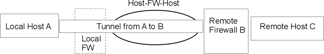
The host-firewall-host configuration option for tunnels allows you to create a tunnel between your host and a firewall, then automatically generate the necessary filter rules for correct communication between your host and a host behind the firewall. The autogenerated filter rules permit all rules between the two non-firewall hosts over the tunnel specified. The default rules--for user datagram protocol (UDP), Authentication Headers (AH), and Encapsulating Security Payload (ESP) headers--should already handle the host to firewall communication. The firewall will have to be configured appropriately to complete the setup. You should use the export file from the tunnel you created to enter the SPI values and keys that the firewall needs.
Figure 4-7. Host -- Firewall -- Host. This illustration shows a Host -- Firewall -- Host configuratoin. Host A has a tunnel running through a local firewall and out to the internet. Then it goes to Remote Firewall B, and then on to Remote Host C.
|