Internet Key Exchange (IKE) tunnels have more complex policy parameters. In most cases, you must use the Web-based System Manager interface to configure IKE tunnels. The Basic Configuration wizard provides an easy way to define an IKE tunnel with preshared keys. For more advanced options, see Advanced IKE Tunnel Configuration.
The basic configuration wizard is an easy way to define an IKE tunnel through Web-based System Manager using preshared keys or certificates as the authentication method. It adds new key management and data management IKE tunnels to the IP Security subsystem, allows you to input minimal data and choose some options, and makes use of common default values for such parameters as tunnel lifetime. The basic configuration wizard can also be used on the remote endpoint to quickly set up a corresponding IKE tunnel end point.
Once a tunnel is defined using the wizard, the tunnel definition appears in the Web-based System Manager IKE tunnels list and can be activated or modified.
When using the basic configuration wizard, keep the following in mind:
Use the following procedure to configure a new tunnel using the wizard:
Online help is available if you need it.
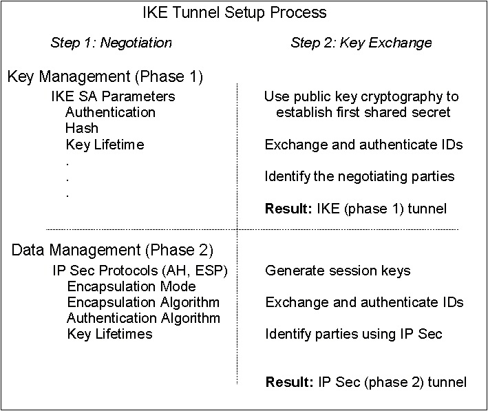
Creating IKE tunnels differs from creating manual tunnels because the setting of security policy is a separate process from defining tunnel endpoints. In IKE, there is a two-step negotiation process, called phases, and each phase can have separate security policies.
When the Internet Key negotiation starts, it must set up a secure channel for the negotiations. This is known as the key management phase or phase 1. During this phase, each party uses preshared keys or digital certificates to authenticate the other and pass ID information. This phase sets up a security association during which the two parties determine how they plan to communicate securely and then which protections are to be used to communicate during the second phase. The result of this phase is an IKE or phase 1 tunnel.
The second phase is known as the data management phase or phase 2 and uses the IKE tunnel to create the IP Sec security associations for AH and ESP that actually protect traffic. The second phase also determines the data that will be using the IP Security tunnel. For example, it can specify:
Figure 4-4. IKE Tunnel Setup Process. This illustration shows the two-step, two-phase process for setting up an IKE tunnel. A description of this process can be found in the document text.
|
In many cases, the endpoints of the key management (IKE) tunnel will be the same as the endpoints of the data management (IP Security) tunnel. The IKE tunnel endpoints are the IDs of the machines carrying out the negotiation. The IP Security tunnel endpoints describe the type of traffic that will use the IP Security tunnel. For simple host-to-host tunnels, in which all traffic between two tunnels is protected with the same tunnel, the phase 1 and phase 2 tunnel endpoints are the same. When negotiating parties are two gateways, the IKE tunnel endpoints are the two gateways, and the IP Security tunnel endpoints are the machines or subnets (behind the gateways) or the range of addresses (behind the gateways) of the tunnel users.
The following parameters are set during phase 1 (the key management phase)
of an IKE tunnel configuration:
| Key Management
(Phase 1) Tunnel | The name of this IKE tunnel. For each tunnel, the endpoints of the negotiation must be specified. These are the two machines that plan to send and validate IKE messages. The name of the tunnel may describe the tunnel endpoints such as VPN Boston or VPN Acme. |
| Host Identity Type | The ID type that will be used in the IKE exchange. The ID type and value must match the value for the preshared key to ensure that proper key lookup is performed. If a separate ID is used to search a preshared key value, the host ID is the key's ID and its type is KEY_ID. The KEY_ID type is useful if a single host has more than one preshared key value |
| Host Identity | The value of the host ID represented as an IP address, a fully qualified
domain name (FQDN), or a user at the fully qualified domain name
(user@FQDN). For example:
jdoe@studentmail.ut.edu |
| IP Address | The IP address of the remote host. This value is required when the host ID type is KEY_ID or whenever the host ID type cannot be resolved to an IP address. For example, if the user name cannot be resolved with a local nameserver, the IP address for the remote side must be entered. |
You can customize key management policy by specifying the parameters to be used during IKE negotiation. For example, there are key management policies for preshared key or signature mode authentication. For Phase 1, the user must determine certain key management security properties with which to carry out the exchange. These properties are fully described in the help available with Web-based System Manager and in the documentation for the ike command.
The data management proposal parameters are set during phase 2 of an IKE tunnel configuration. They are the same IP Security parameters used in manual tunnels and describe the type of protection to be used for protecting data traffic in the tunnel. You can start more than one phase 2 tunnel under the same phase 1 tunnel.
The following endpoint ID types describe the type of data that is to use
the IP Security Data tunnel:
| Host, Subnet, or Range | Describes whether the data traffic traveling in the tunnel will be for a particular host, subnet, or address range. |
| Host/Subnet ID | Contains the host or subnet identity of the local and remote systems passing traffic over this tunnel. Determines the IDs sent in the phase 2 negotiation and the filter rules that will be built if the negotiation is successful. |
| Subnet mask | Describes all IP addresses within the subnet (for example, host 9.53.250.96 and mask 255.255.255.0) |
| Starting IP Address Range | Provides the starting IP address for the range of addresses that will be using the tunnel (for example, 9.53.250.96 of 9.53.250.96 to 9.53.250.93) |
| Ending IP Address Range | Provides the ending IP address for the range of addresses that will be using the tunnel (for example, 9.53.250.93 of 9.53.250.96 to 9.53.250.93) |
| Port | Describes data using a specific port number (for example, 21 or 23) |
| Protocol | Describes data being transported with a specific protocol (for example, TCP or UDP). Determines the protocol sent in the phase 2 negotiation and the filter rules that will be built if the negotiation is successful. The protocol for the local endpoint must match the protocol for the remote end point. |
The data management parameters are fully described in the help available with Web-based System Manager and in the documentation for the ike command.
IKE tunnels are configured using the Web-based System Manager tool. Use the following procedure to add an IKE tunnel:
A tunnel is created by defining the key management and data management endpoints and their associated security transforms and proposals.
The same key management tunnel can be used to protect multiple data management negotiations and key refreshes, as long as they take place between the same two endpoints, for example between two gateways.
On the Transforms tab, use matching transforms on both sides, or contact the administrator on the remote end to define a matching transform. A transform containing several choices can be created to allow flexibility when proposing or matching on a transform.
To enable digital certificates and signature mode support, choose an authentication method of RSA Signature or RSA Signature with CRL Checking.
For more information about digital certificates, see Digital Certificate Configuration.
To set up data management tunnel endpoints and proposals and to complete IKE tunnel setup, launch the Web-based System Manager tool, as described in Setting up, Key Management. A data management tunnel is created by selecting a key management tunnel and defining any unique options. Most data management options can remain as defined by the default.
However, you must specify endpoint types (such as IP address, subnet, or IP address range) under the Endpoints tab. You can select a port number and protocol or accept the default.
On the Proposals panel, you can create a new proposal by selecting the Add button or simply click on OK to create a proposal. If there are multiple proposals, you can use the Move Up or Move Down buttons to change the search order.
Beginning with AIX 5.1, IP security supports grouping IKE IDs in a tunnel definition to associate multiple IDs with a single security policy without having to create separate tunnel definitions. Grouping is especially useful when setting up connections to several remote hosts, because you can avoid setting up or managing multiple tunnel definitions. Also, if changes must be made to a security policy, you do not need to change multiple tunnel definitions.
A group is composed of a group name and a list of IKE IDs and ID types. The IDs can all be the same type or a mix of IPv4 addresses, IPv6 addresses, FQDN, user@FQDN, and X500 DN types. During a Security Association negotiation, the IDs in a group are searched linearly for the first match.
A group must be defined before using that group name in tunnel definition. Use the ikedb command to define groups. This command accepts XML text as input to create a group definition in the IKE databases. The group's size is limited to 1 Kbyte.
A group name can be used in both key management tunnel and data management tunnel definitions, but can be used only as a remote ID.
Activate the tunnel using the Web-based System Manager tool (see Setting up, Key Management) or from the command line using the ike command. Online help is available for the Web-based System Manager tool. The following instructions describe how to activate a tunnel from the command line.
ike cmd=activate numlist=1
You can also use remote id or IP addresses, as shown in the following examples:
ike cmd=activate remid=9.3.97.256
ike cmd=activate ipaddr=9.3.97.100, 9.3.97.256
Since it may take several seconds for the commands to complete, the command returns after the negotiation is started.
ike cmd=list
The output looks similar to the following:
Phase 1 Tunnel ID       [1]
Phase 2 Tunnel ID       [1]
This command shows the phase 1 and phase 2 tunnels that are currently active. To do a verbose listing of the tunnel, use the verbose option, as shown in the following example:
ike cmd=list verbose

Phase 1 Tunnel ID       1
Local ID Type:          Fully_Qualified_Domain_Name
Local ID:               bee.austin.ibm.com
Remote ID Type:         Fully_Qualified_Domain_Name
Remote ID:              ipsec.austin.ibm.com
Mode:                   Aggressive
Security Policy:        BOTH_AGGR_3DES_MD5
Role:                   Initiator
Encryption Alg:         3DES-CBC
Auth Alg:               Preshared Key
Hash Alg:               MD5
Key Lifetime:           28800 Seconds
Key Lifesize:           0 Kbytes
Key Rem Lifetime:       28737 Seconds
Key Rem Lifesize:       0 Kbytes
Key Refresh Overlap:    5%
Tunnel Lifetime:        2592000 Seconds
Tunnel Lifesize:        0 Kbytes
Tun Rem Lifetime:       2591937 Seconds
Status:                 Active

Phase 2 Tunnel ID       1
Local ID Type:          IPv4_Address
Local ID:               10.10.10.1
Local Subnet Mask:      N/A
Local Port:             any
Local Protocol:         all
Remote ID Type:         IPv4_Address
Remote ID:              10.10.10.4
Remote Subnet Mask:     N/A
Remote Port:            any
Remote Portocol:        all
Mode:                   Oakley_quick
Security Policy:        ESP_3DES_MD5_SHA_TUNNEL_NO_PFS
Role:                   Initiator
Encryption Alg:         ESP_3DES
AH Transform:           N/A
Auth Alg:               HMAC-MD5
PFS:                    No
SA Lifetime:            600 Seconds
SA Lifesize:            0 Kbytes
SA Rem Lifetime:        562 Seconds
SA Rem Lifesize:        0 Kbytes
Key Refresh Overlap:    15%
Tunnel Lifetime:        2592000 Seconds
Tunnel Lifesize:        0 Kbytes
Tun Rem Lifetime:       2591962 Seconds
Assoc P1 Tunnel:        0
Encap Mode:             ESP_tunnel
Status:                 Active
Activating the IKE tunnel causes filter rules for the new tunnel to be inserted into the dynamic filter table. These entries can be viewed using the lsfilt command with the -d option for dynamic filter rules:
1 permit 0.0.0.0 0.0.0.0 0.0.0.0 0.0.0.0 no udp eq 4001 eq 4001 both both no all
  packets 0 all
2 *** Dynamic filter placement rule *** no
0 permit 0.0.0.0 0.0.0.0 0.0.0.0 0.0.0.0 yes all any 0 any 0 both both no all
  packets 0 all

*** Dynamic table ***

0 permit 0.0.0.0 0.0.0.0 0.0.0.0 0.0.0.0 no udp eq 500 eq 500 local both no all
  packets 0
0 permit 0.0.0.0 0.0.0.0 0.0.0.0 0.0.0.0 no ah any 0 any 0 both inbound no all
  packets 0
0 permit 0.0.0.0 0.0.0.0 0.0.0.0 0.0.0.0 no esp any 0 any 0 both inbound no all
  packets 0
1 permit 10.10.10.1 255.255.255.255 10.10.10.4 255.255.255.255 no all any 0 any
  0 both outbound yes all packets 1
1 permit 10.10.10.4 255.255.255.255 10.10.10.1 255.255.255.255 no all any 0 any
  0 both inbound yes all packets 1
This example shows a machine that has one IKE tunnel and no other tunnels. The dynamic filter rule (rule #2 in this example of the static table) can be moved by the user to control placement relative to all other user-defined rules. The rules in the dynamic table are constructed automatically as tunnels are negotiated and corresponding rules are inserted into the filter table. These rules can be displayed, but not edited.
chfilt -v 4 -n 2 -l y
For more details on logging of IKE traffic, see the section on Logging Facilities.
ike cmd=remove numlist=1
The ikedb command, available in AIX 5.1 and later, allows a user to create IKE tunnels using an XML interface. The ikedb command can also be used for IKE data retrievals (useful for database backups), updates, deletes, and imports. An example XML file can be found in /usr/samples/ipsec. See the ikedb command description in the AIX 5L Version 5.1 Commands Reference for syntax details.
You can view the tunnel definitions using either the ikedb command with the -g flag or the Web-based System Manager. To activate the tunnel, use either the ike cmd=activate command or the Web-based System Manager.
To configure an AIX IKE tunnel using Linux configuration files (AIX 5.1 and later), use the ikedb command with the -c flag (conversion option), which lets you use the /etc/ipsec.conf and /etc/ipsec.secrets Linux configuration files as IKE tunnel definitions. The ikedb command parses the Linux configuration files, creates an XML file, and optionally adds the XML tunnel definitions to the IKE database. You can then view the tunnel definitions by using either the ikedb -g command or the Web-based System Manager.
There are typical scenarios that describe the type of situations most customers encounter when trying to set up tunnels. They can be described as the branch office, business partner, and remote access cases.
In the branch office case, the customer has two trusted networks that they want to connect together--the engineering group of one location to the engineering group of another. In this example, there are gateways that connect and all the traffic passing between the gateways use the same tunnel. The traffic at either end of the tunnel is decapsulated and passes in the clear within the company intranet.
In the first phase of the IKE negotiation, the IKE security association is created between the two gateways. The traffic that passes in the IP Security tunnel is the traffic between the two subnets, and the subnet IDs are used in the phase 2 negotiation. After the security policy and tunnel parameters are entered for the tunnel, a tunnel number is created. To start the tunnel, use the ike command.
In the business partner scenario, the networks are not trusted, and the network administrator may want to restrict access to a smaller number of hosts behind the security gateway. In this case, the tunnel between the hosts carries traffic protected by IP Security for use between two particular hosts. The protocol of the phase 2 tunnel is AH or ESP. This host-to-host tunnel is secured within a gateway-to-gateway tunnel.
In the remote access case, the tunnels are setup on demand and a high level of security is applied. The IP addresses may not be meaningful, therefore, fully qualified domain names or user@ fully qualified domain names are preferred. Optionally, you can use KEYID to relate a key to a host ID.
Digital certificates bind an identity to a public key, through which you can verify the sender or the recipient of an encrypted transfer. Beginning with AIX 4.3.3, IP Security uses digital certificates to enable public-key cryptography, also known as asymmetric cryptography, which encrypts data using a private key known only to the user and decrypts it using an associated public (shared) key from a given public-private key pair. Key pairs are long strings of data that act as keys to a user's encryption scheme.
In public-key cryptography, the public key is given to anyone with whom the user wants to communicate. The sender digitally signs all secure communications with the corresponding private key for their assigned key pair. The recipient uses the public key to verify the sender's signature. If the message is successfully decrypted with the public key, the receiver can verify that the sender was authenticated.
Public-key cryptography relies on trusted, third parties, known as a certification authorities (CAs), to issue reliable digital certificates. The recipient specifies which issuing organizations or authorities are deemed trusted. A certificate is issued for a specific amount of time; when its expiration date has passed, it must be replaced.
AIX 4.3.3 and later versions provide the IBM Key Manager tool, which manages digital certificates. The following sections provide conceptual information about the certificates themselves. Management tasks for these certificates are described in Using the IBM Key Manager Tool.
The digital certificate contains specific pieces of information about the identity of the certificate owner and about the certification authority. See the following figure for an illustration of a digital certificate. The following list further describes the contents:
Figure 4-5. Contents of a Digital Certificate. This illustration shows the four entities of a digital certificate. From the top they are, Owner's Distinguished Name, Owners Public Key, Issuer's (CA) Distinguished Name, and Issuer's Signature.
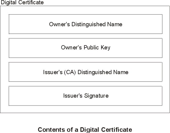 |
Figure 4-6. Example of Deriving Distinguished Name from Directory Tree. This illustration is a directory tree with O=IBM at the top level and branching to two entities on the second level. Level two contains OU=AIX and OU=Acctg on separate branches; each has a branch leading to a single entity on the last level.. The last level contains CN=Prasad and CN=Peltier respectively.
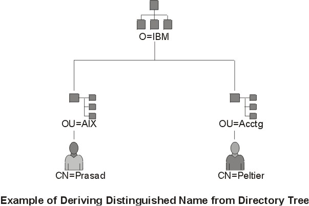 |
/C=US/O=IBM/OU=SERV/CN=prasad.austin.ibm.com
A digital certificate alone cannot prove identity. The digital certificate only allows you to verify the identity of the digital certificate owner by providing the public key that is needed to check the owner's digital signature. You can safely send your public key to another because your data cannot be decrypted without of the other part of the key pair, your private key. Therefore, the owner must protect the private key that belongs to the public key in the digital certificate. All communications of the owner of a digital certificate can be deciphered if the private key is known. Without the private key, a digital certificate cannot be misused.
A digital certificate is only as trustworthy as the certification authority (CA) that issued it. As part of this trust, the policies under which certificates are issued should be understood. Each organization or user must determine which certification authorities can be accepted as trustworthy.
Certification Authority organizations such as Verisign, Entrust, or Thawte can issue digital certificates. The IBM Key Manager tool also allows organizations to create self-signed certificates, which can be useful for testing or in environments with a small number of users or machines.
As a user of a security service, you need to know its public key to obtain and validate any digital certificates. Also, simply receiving a digital certificate does not assure its authenticity. To verify its authenticity, you need the public key of the certification authority that issued that digital certificate. If you do not already hold an assured copy of the CA's public key, then you might need an additional digital certificate to obtain the CA's public key.
A digital certificate is expected to be used for its entire validity period. If needed, however, a certificate can be invalidated before its actual date of expiration. Invalidating the certificate may be necessary, for example, if an employee leaves the company or if the certificate's private key has been compromised. To invalidate a certificate, you must notify the appropriate Certificate Authority (CA) of the circumstances. When a CA revokes a certificate, it adds the invalid certificate serial number to a Certificate Revocation List (CRL).
CRLs are signed data structures that are issued periodically and made available in a public repository. CRLs can be retrieved from HTTP or LDAP servers. Each CRL contains a current timestamp and a nextUpdate timestamp. Each revoked certificate in the list is identified by its certificate serial number.
When configuring an IKE tunnel and using digital certificates as your authentication method, you can confirm the certificate has not been revoked by selecting RSA Signature with CRL Checking. If CRL Checking is enabled, the list is located and checked during the negotiation process to establish the key management tunnel.
Note: To use this feature of IP Security, your system must be configured to use a SOCKS server (version 4 for HTTP servers), an LDAP server, or both. If you know which SOCKS or LDAP server you are using to obtain CRLs, you can make the necessary configuration selections by choosing CRL Configuration from the Digital Certificates menu within the Web-based System Manager.
Internet applications that use public-key cryptography systems must use digital certificates to obtain the public keys. There are many applications that use public-key cryptography, including the following ones:
The protocols used in tunneling follow the IP Security and IKE standards, which allow for a secure, encrypted connection between a remote client (for example, an employee working from home) and a secure host or network.
Simplified, a signed digital certificate contains fields for the owner's distinguished name, the owner's public key, the CA's distinguished name and the CA's signature. A self-signed digital certificate contains its owner's distinguished name, public key, and signature.
A certificate request must be created and sent to a CA to request a digital certificate. The certificate request contains fields for the requestor's distinguished name, public key, and signature. The CA verifies the requestor's signature with the public key in the digital certificate to ensure that:
The CA is also responsible for verifying to some level the identity of the requestor. Requirements for this verification can range from very little proof to absolute assurance of the owner's identity.