This chapter contains general information about the workstations supported by the graPHIGS APIscreen It describes functions and limitations of particular workstations when running graPHIGS API applications. Consider these when writing your application programs.
You should obtain and use the latest level of microcode for your workstation when applicable. This ensures that you have fixes for microcode problems and possible performance enhancements. Ask the person responsible for installing the graPHIGS API on your system to refer to the Program Directory supplied with the latest release for information about the latest microcode release(s).
The X Workstation represents the family of X workstations supported by the graPHIGS API.
This section discusses the interaction between a graPHIGS API application and the X Version 11 Window System. It is not within the scope of this book to explain X or graPHIGS API concepts. Background for the standard X and graPHIGS API terminology in this chapter may be found in The graPHIGS Programming Interface: Understanding Concepts and in the X Window System documentation.
The X Window System(**) supports multiple applications running in overlapping and hidden windows on one or more screens. X applications, called clients, share common resources such as the keyboard, mouse, display surface, and hardware colormaps. The functions provided in X for window creation, window deletion, window re-sizing, colormap allocation, and event handling make this environment very different from a user running a single full-screen application.
However, X is but one of many workstations supported by the graPHIGS APIscreen This implies that a graPHIGS API application does not need to recognize that it is running in an X window, and that special support is not required to run under X. A graPHIGS API application is not developed specifically for the X environment, and is expected to perform in an X window as if it were running full screen.
All processing that is unique to the X environment will be handled by the graPHIGS API. For example, when an overlapping window is moved, the application must maintain the contents of the window beneath. X generates events in order to notify the client that the window must be re-drawn. It is the responsibility of the graPHIGS API to manage all X resources and to ensure that the window contents accurately reflect the graphic contents. When the user changes the size of the window, the graPHIGS API manages the graphics and echo areas according to the window mapping method. (Refer to "Window Mapping and Resize" for more information). Such events are handled by the graPHIGS API on behalf of the application. So in fact, the graPHIGS API ensures that upward compatibility will be maintained and existing applications will run unchanged.
Graphic output for a logical graPHIGS API workstation will be displayed in one corresponding window. For example, if an application opens four X workstations, four windows will be created with a workstation associated to each window.
For the graPHIGS API to create X resources such as windows, it must communicate with an X server by opening a connection to the server. The process by which the graPHIGS API chooses the server is described in "Opening the X Workstation"screen This connection is private and the application cannot access the connection. This allows an application to access both graPHIGS API and X11 functionality without confusion; it can mix graPHIGS API calls with X calls to use both the advanced graphic capabilities provided by the graPHIGS API and the user interface routines provided by X11 toolkits. Having opened a workstation, an application can access X resources by opening its own connection to a server. An application that is making X calls has access to all X windows on the screen because X has very generous rules for sharing resources. An application could draw into the same window that the graPHIGS API accesses. However, this is strongly discouraged because it would be impossible to synchronize updates. An application mixing X subroutine calls with graPHIGS API subroutine calls should not use X to access the graPHIGS API window.
Both an application coding to the X interface and the graPHIGS API should behave as well-behaved X clients. The graPHIGS API has been designed to minimize its use of server resources and to follow the guidelines in the Inter-Client Communications Conventions Manual screen This X Window System manual defines policies that allow an application to coexist properly with other applications sharing the same server. The graPHIGS API will adhere to these guidelines.
Since both the graPHIGS API application and the graPHIGS API are considered to be a single X client, it is necessary to understand how the API creates a window, maps the graphics to a window, and handles X events. These topics will be covered in detail in the following sections.
Temporary views are supported with the following limitations:
Direct Access Capabilities on the RS/6000:
See The graPHIGS Programming Interface: Understanding Concepts for more information about temporary views.
If the projection reference point is between the near and far clip planes, the projection type is changed to PARALLEL and an error is generated.
In general, the graPHIGS API is intended to operate with an application on an IBM(*) AIX-based workstation. The graphics generated by the graPHIGS API, when using the X workstation, may be displayed on any equipment that supports a complete X server (X Version 11, Release 4 or later for the RS/6000 platform). The graPHIGS API is designed to exploit the distributed, network transparent, and device independent qualities of X. Because of these capabilities, the user may run a graPHIGS API application on the same machine as the X server, or may run a graPHIGS API application on another machine that is connected to the machine on which the X server is being used for display.
IBM does not explicitly support the use of non-IBM equipment running an X server to display the output of the graPHIGS APIscreen However, if the X server supports a full implementation of the X protocol, then there should be little difficulty in using this equipment in this way. The graPHIGS API requires that the target X server support any of the StaticGray, GrayScale, StaticColor, or PseudoColor visual classes. The DirectColor and TrueColor visual classes cannot be used for the X workstation type in non-DWA (non-Direct Window Access) mode.
On some IBM equipment, the graPHIGS API supports advanced rendering capabilities which are available through a method called Direct Window Access (DWA)screen These capabilities are assisted through hardware on the X workstation when in DWA mode. For a list of these DWA capabilities, see "Additional Capabilities Available on RS/6000"screen DWA capabilities are only available when the graPHIGS API nucleus runs on the same machine as the X server. In order to use the DWA capabilities on a remote machine, the application must connect to a remote graPHIGS API nucleus running on that remote machine.
Brief listings of configurations supporting the X
workstation for the graPHIGS API follow:
Table 3. Configurations Supporting the X Workstation for graPHIGS API Running on the XStation 120
| SOFTWARE | DISPLAY ADAPTER | FRAME BUFFER DEPTH | BUFFERS (single or double) | SUPPORTED X WORKSTATION CAPABILITIES | VISUAL CLASS |
|---|---|---|---|---|---|
| runs Xserver software only | application runs on network attached to host | 8 bit | single | non-DWA / XSOFT | PseudoColor |
Table 4. Configurations Supporting X Workstation for graPHIGS API Running on the RS/6000
| DISPLAY ADAPTER | FRAME BUFFER DEPTH | BUFFERS (single or double) | SUPPORTED X WORKSTATION CAPABILITIES | VISUAL CLASS |
| GrayScale Graphics Display Adapter | 4 bit | single | non-DWA | GrayScale |
| Color Graphics Display Adapter | 8 bit | single | non-DWA / XSOFT | PseudoColor |
| High Performance 3D Color Graphics Display Processor (8 bit) | 8 bit | single | DWA / XSOFT | PseudoColor |
| 4 bit | double | DWA | PseudoColor | |
| 8 bit | single | non-DWA / XSOFT | PseudoColor | |
| High Performance 3D Color Graphics Display Processor (24 bit) | 12 bit | double | DWA | TrueColor |
| 24 bit | single1 | DWA / XSOFT | TrueColor | |
| 8 bit | single | non-DWA / XSOFT | PseudoColor | |
| POWER GXT100 (8 bit) | 8 bit | single | non-DWA / XSOFT | PseudoColor |
| POWER Gt3i | 8 bit | single | non-DWA / XSOFT | PseudoColor |
| POWER Gt1x | 8 bit | single | non-DWA / XSOFT | PseudoColor |
| POWER Gt4e (8 bit) | 8 bit | double | DWA / XSOFT | PseudoColor |
| 8 bit | single | non-DWA / XSOFT | PseudoColor | |
| High Performance Graphics Subsystem (Model 730, 8 bit) | 8 bit | double | DWA / XSOFT | PseudoColor |
| 8 bit | single | non-DWA / XSOFT | PseudoColor | |
| High Performance Graphics Subsystem (Model 730, 24 bit) | 24 bit | double | DWA / XSOFT | DirectColor |
| 8 bit | single | non-DWA / XSOFT | PseudoColor | |
| POWER GtO (8 bit) | 8 bit | double | DWA / XSOFT | PseudoColor |
| 8 bit | single | non-DWA / XSOFT | PseudoColor | |
| POWER GtO (24 bit) | 24 bit | double | DWA / XSOFT | DirectColor |
| 8 bit | single | non-DWA / XSOFT | PseudoColor | |
| POWER Gt4x (8 bit), POWER Gt4xi (8 bit) | 8 bit | double | DWA / XSOFT | PseudoColor |
| 8 bit | single | non-DWA / XSOFT | PseudoColor | |
| POWER Gt4 (24 bit), POWER Gt4x (24 bit), and POWER Gt4xi (24 bit) | 24 bit | double | DWA / XSOFT | DirectColor |
| 8 bit | single | non-DWA / XSOFT | PseudoColor | |
| POWER GXT500D | 24 bit | double | DWA / XSOFT | TrueColor |
| 24 bit | double | DWA / XSOFT | DirectColor | |
| 8 bit | double | DWA / XSOFT / non-DWA | PseudoColor | |
| POWER GXT1000 and POWER GXT800P | 24 bit | double | DWA / XSOFT | TrueColor |
| 24 bit | double | DWA / XSOFT | DirectColor | |
| 8 bit | double | non-DWA / XSOFT | PseudoColor | |
| POWER GXT500 | 24 bit | single | DWA / XSOFT | TrueColor |
| 24 bit | single | DWA / XSOFT | DirectColor | |
| 8 bit | double | DWA / XSOFT / non-DWA | PseudoColor | |
| 12 bit | double | DWA | DirectColor | |
| POWER GXT255P | 8 bit | double | DWA / XSOFT / non-DWA | PseudoColor |
| 24 bit | single | XSOFT | TrueColor | |
| 24 bit | single | XSOFT | DirectColor | |
| POWER GXT250P | 8 bit | double | DWA / XSOFT / non-DWA | PseudoColor |
| 8 bit | single | non-DWA / XSOFT | PseudoColor2 | |
| POWER GXT550P | 24 bit | double | DWA / XSOFT | TrueColor |
| 24 bit | double | DWA / XSOFT | DirectColor | |
| 8 bit | double | DWA / XSOFT / non-DWA | PseudoColor | |
| POWER GXT500P | 24 bit | single | XSOFT | TrueColor |
| 24 bit | single | XSOFT | DirectColor | |
| 8 bit | double | DWA / XSOFT / non-DWA | PseudoColor | |
| 12 bit | double | DWA | DirectColor | |
| Notes: 1
See
"FBUFFER (Frame Buffer Configuration)" for this support.
2 Screen size is 1024x768. | ||||
When a graPHIGS API application wants to open a logical workstation, it must specify a workstation type and connection identifier. The workstation type for the X workstation support must be 'X' and the connection ID can either be '*' or the standard X windows server specification 'host:server.screen'. If you specify an asterisk, then the graPHIGS API connects to the server listed in the AIX environment variable DISPLAY screen
The value of the AIX environment variable LANG determines the graPHIGS API primary character set.
The workstation type and the connection identifier can be specified through the defaults processing (EDF file or ADIB) and as parameters on the Open Workstation (GPOPWS) or the Create Workstation (GPCRWS) subroutines. The following examples illustrate two ways of specifying the connection identifier and workstation type.
|
Note: See the description under "Additional notes for the POWER GXT1000, POWER GXT255P, POWER GXT250P, POWER GXT800P, POWER GXT500P, POWER GXT550P, and POWER GXT500 family" for more information on Opening the X Workstation with the POWER GXT1000 and GXT500.
The window associated with a workstation can be created by either the application or the graPHIGS APIscreen This has been designed to provide maximum flexibility. The application can create the window and pass the window identifier to the API via the XWINDID PROCOPT screen By default, the graPHIGS API will create the window as a child of the root window (top-level window), using the same visual, depth and screen as the root window. It will not create the window if the user specifies the XWINDID PROCOPT screen
If the API creates the window on behalf of the application, the user may specify some information about the window that will define the initial position, initial size and window appearance. This information is communicated to X through two mechanisms, the XCreateWindow subroutine call and propertiesscreen The following will explain how the graPHIGS API will use these mechanisms to create a window.
X allows the graPHIGS API to associate information, called properties, with a window that other clients can access. Properties that are processed by a window manager are called hintsscreen A hint is appropriately named because a window manager has the authority to interpret or ignore any property. This is to say that it impossible to state exactly how the window will ultimately appear because each window manager will interpret hints differently. The graPHIGS API has chosen a standard set of properties to define on a window. These properties can be used by a window manager to define the initial position, initial size, window title, icon name, icon bitmap, minimum aspect ratio, maximum aspect ratio, window border color and the window border width.
The graPHIGS API will define these properties based on default
information provided by the user.
The graPHIGS API will use the standard methods for collecting user
preferences, namely the .Xdefaults file.
The user can specify a string, which is usually the
application name, via a graPHIGS API
PROCOPT
called XNAME
(see
"XNAME")screen
The graPHIGS API will use this string to identify defaults specified
in the .Xdefaults file.
Table 5
describes the properties that the user can specify and
the graPHIGS API system default action if
the user has not specified the attribute.
Table 5. Window Creation Defaults for .Xdefaults File
| Description | Format | graPHIGS API Default Action |
|---|---|---|
| Initial Window Geometry | namescreen | See Discussion Below |
| Minimum Window Size | namescreen | 100x100 |
| Window Title | namescreen | Blank Title |
| Icon Name | namescreen | Default to the Window Name |
| Icon Bitmap Filename | namescreen | No icon bitmap |
| Minimum Aspect Ratio | namescreen | None specified |
| Maximum Aspect Ratio | namescreen | None specified |
| Window Border color (Pixel Value) | namescreen | Zero |
| Window Border width | namescreen | Zero PROCOPT XNAME |
| Note: The value of the (see "XNAME") is substituted here as namescreen | ||
Each of the defaults may be prefixed by a name or a wildcard. This name can be passed in via the graPHIGS API XNAME PROCOPT (see "XNAME"), otherwise, the graPHIGS API will default the name to "graPHIGS".
If the user does not specify the initial window geometry, the graPHIGS API will create a window half the width of the screen and with the same aspect ratio. This is to insure that the window is large enough for the user to easily locate. Your window manager may prompt you to size or move the initial window if the graPHIGS API specifies the initial window geometry. The values that the graPHIGS API supplies will be used for the outline of the rubber band box that the window manager will display.
The window border color is specified as a pixel value and not as a named color. This is due to the fact that the graPHIGS API may associate a colormap to the window and the named color will not necessarily correspond to the pixel value.
A sample .Xdefaults file with the above defaults is supplied when you install the graPHIGS API diskettes. For the graPHIGS API to find your defaults, you will have to place the default information in your .Xdefaults file in your $HOME directory.
The Convert Coordinate Values (GPCCV) subroutine can be used by the application to convert coordinate units among the NPC, DC, and window units (WU) ranges.
The Inquire Mapped Display Surface Size (GPQMDS) subroutine returns the size of the area that displays the DC range. In the 1=MAPPED method, the display is constrained to an area with the same aspect ratio as the display surface screen In the 2=DIRECT method, the value returned is the current size of the window, constrained to the same area as the root window. The application can use this value as the current size of the displayable part of DC.
Information derived from the .Xdefaults file will be used to
change some of the X window attributes
via the XCreateWindow subroutine call.
The .Xdefaults information is only processed when the window
is created by the graPHIGS API and therefore the corresponding
window attributes will only be changed at this time.
Window attributes are also changed by the graPHIGS API in order to
process events and color.
The following table briefly illustrates which attributes
will be used by the graPHIGS APIscreen
The column on the left applies when the API creates
the window and the column on the right applies when the
application creates the window.
| Attribute | graPHIGS API | Application |
|---|---|---|
| 1) background_pixmap | * | |
| 2) background_pixel | * | |
| 3) border_pixmap | * | |
| 4) border_pixel | * | |
| 5) bit_gravity | + | + |
| 6) win_gravity | ||
| 7) backing_store | + | + |
| 8) backing_planes | + | + |
| 9) backing_pixel | + | + |
| 10) override_redirect | ||
| 11) save_under | + | + |
| 12) event_mask | * | * |
| 13) do_not_propogate | ||
| 14) colormap | * | * 1 |
| 15) cursor | * | * |
| Key: * = the graPHIGS API will change this attribute + = the graPHIGS API may use this attribute in the future | ||
| 1 This is dependent on the XNOCLRMP PROCOPT (see "XNOCLRMP (Do Not Create an X Color Map)")screen | ||
When the graPHIGS API has created and associated a colormap to the window, the API will require that a window manager be installed. This ensures that the graPHIGS API colormap will be installed by the window manager when the pointing icon is in the graPHIGS API window. This adheres to the Inter-client Communications Conventions Manual , in that the client should avoid grabbing the input focus and installing the colormap, and allow the window manager to perform these actions.
Under specific circumstances described in the list below, the graPHIGS API provides access to graphics processor capabilities not normally available through the X Protocol. These additional capabilities allow exploitation of hardware features of a graphics processor. The availability of these capabilities is indicated in the actual WDT of the workstation. Specific capabilities are described in Chapter 3. "Workstation Description Tables" as direct access features of the X workstation type.
To obtain direct access to the High Performance 3D Color Graphics Processor (8 bit or 24 bit), the High Performance Graphics Subsystem (Model 730, 8 bit or 24 bit), the POWER Gt4e (8 bit), the POWER GtO (8 bit or 24 bit), the POWER Gt4x (8 bit or 24 bit), the POWER Gt4 (24 bit), the POWER GXT1000, the POWER GXT255P, the POWER GXT250P, or the POWER GXT500, the following conditions are necessary:
The application can pass the graPHIGS API a window ID and the API will use this for the workstation display window. If the application creates the window, then it cannot change the window ID without closing the workstation and re-opening the workstation with a new ID. It is the responsibility of the application to map the window before opening the workstation.
A potential problem with an application creating its own window is that it cannot know for certain whether the graPHIGS nucleus on which the X workstation will be created is local to the X server where the window was created. For example, if the application intended to open an XDWA workstation but the application's window was created on an X server that is remote to the graPHIGS nucleus, then an XDWA workstation will fail during its initialization. This situation can happen readily if the graPHIGS nucleus that is connected to has been changed via a TONUC or DEFNUC default in an EDF. The application could use the GPQNCE (Inquire Nucleus Environment) subroutine to get the Internet address and the hostname of the system that the nucleus is running in order to avoid this situation. Also, you can see the GPES subroutine (escape 1018) for information on getting a list of supported visuals in order to guarantee that the application's window will be usable by the graPHIGS nucleus.
It is important to remember when defining your window, that the Inter-Client Communications Manual proposes that the client should avoid installing the colormap, and allow the window manager to perform these actions. The window manager will install the colormap automatically for top level windows. For descendents of the top level windows which have different colormaps, there is no current convention as to how their colormaps will be made active. Typically, descendents of a top level window will share the colormap associated with the top level window. See "XWINDID (X Window Identifier)" for additional information.
The following code illustrates the steps necessary to create a window and pass the window identifier to the graPHIGS APIscreen
/* Declare the defaults data structure */
struct
{
int adib_len ;
struct
{
int len ;
int code ; /* code for following nicknames */
/* nickname - must be in adib */
char fromws[8] ;
char fromconn[8] ;
char tows[8] ;
char toconn[8] ;
/* PROCOPT for window id*/
struct
{
int len ;
int code ;
int window_id ;
} ads1 ;
} nicknames ;
} adib ;
/* Open a connection to the server */
if (!(dpy = XOpenDisplay(NULL)))
{
printf("Cannot open display \n");
exit(0);
}
/* Create an X window using a simple version of XCreateWindow */
win = XCreateSimpleWindow(dpy,
RootWindow(dpy,0),
DisplayWidth(dpy,0)/4,
DisplayHeight(dpy,0)/4,
DisplayWidth(dpy,0)/2,
DisplayHeight(dpy,0)/2,
0,0,0);
/* Map the window */
XMapWindow(dpy, win);
XSync(dpy,FALSE);
/* initialize the adib */
adib.adib_len = sizeof(adib) ;
adib.nicknames.code = 2001 ;
adib.nicknames.len = sizeof(adib.nicknames) ;
strncpy(adib.nicknames.fromws," ",8) ;
strncpy(adib.nicknames.fromconn," ",8) ;
strncpy(adib.nicknames.tows ,"X ",8) ;
strncpy(adib.nicknames.toconn ,"* ",8) ;
adib.nicknames.ads1.len = sizeof(adib.nicknames.ads1) ;
adib.nicknames.ads1.code = 25 ;
adib.nicknames.ads1.window_id = win ;
/* pass the defaults to the graPHIGS API */
GPOPPH(erfile,&adib) ;
|
This name will be used to resolve the defaults in the .Xdefaults file. The following example illustrates the format of XNAME and the corresponding format of the defaults in the .Xdefaults file.
  AFMMNICK  TOWSTYPE=X,
TOCONNID=unix:0,
PROCOPT=((XNAME,MyName))
.Xdefaults file in your $HOME directory
MyName.geometry: 500x500+0+0 MyName.title : MyTitle |
If the XNAME PROCOPT (see "XNAME") is not specified then the graPHIGS API will use the string "graPHIGS" to resolve the defaults. The .Xdefaults file would look like the following.
graPHIGS.geometry: 500x500+0+0 graPHIGS.title : MyTitle |
This option is only processed by the graPHIGS API if the application has also specified the XWINDID PROCOPT (see "XWINDID (X Window Identifier)")screen The API will not create a colormap if this PROCOPT has been defined. This implies that the application cannot access the colormap via the graPHIGS APIscreen The API will initialize the display colormap as non-modifiable by the application. This allows the application to have full control over the colormap without graPHIGS API intervention. Refer to "Interaction of X and graPHIGS API Color Resources" and "XNOCLRMP (Do Not Create an X Color Map)" for more detailed information.
When the workstation is created, the graPHIGS API X-Windows device driver establishes the display surface size in the Workstation Description Table (WDT). The graPHIGS API PROCOPT XWINDASP (see "XWINDASP (Window Aspect Ratio)") is provided to allow the application or user to specify the aspect ratio of the display surface that is mapped to the window. If the window already exists (identified using the XWINDID PROCOPT [see "XWINDASP (Window Aspect Ratio)"]), then the graPHIGS API X-Windows device driver uses the largest subarea of the window that has the aspect ratio specified in the XWINDASP PROCOPT screen If the window does not exist, then a window is created, using hints in the X defaults file (or workstation defaults if the X defaults file hints do not exist). The graPHIGS API X-Windows device driver uses the largest subarea of the created window that has the aspect ratio specified in the XWINDASP PROCOPT screen If the XWINDASP PROCOPT is not specified, then the aspect ratio of the root window is used. Refer to Chapter 7. "Controlling the Environment with Defaults and Nicknames" for the format of the PROCOPT in the External Defaults File (EDF) or the Applications Interface Defaults Block (ADIB).
Refer to Chapter 7. "Controlling the Environment with Defaults and Nicknames" for information relating to the other supported PROCOPTS.
On AIX, the graPHIGS API has been using an IBM extension to Xlib (X Asynchronous Event Handling) in order to receive X events. Using this extension, the graPHIGS API defines an event handler and receives X events (that pertain to the windows for any graPHIGS X workstations that are open) via an X signal handler. This technique allows the graPHIGS X workstations to handle events regardless of whether the application process is executing graPHIGS API code or not.
Unfortunately, the use of this asynchronous event extension has caused problems for some graPHIGS applications. Because of these problems, another method of handling X events was needed, one which used a synchronous method to receive X events. To use this method, a graPHIGS application has to:
For this reason, many graPHIGS applications would not want to use this method and, in general, most applications either handle all events themselves (which they can do if the applications create their own X windows and pass the window identifiers in a procopt in the Create Workstation (GPCRWS) subroutine or the Open graPHIGS (GPOPPH) subroutine and they do not use graPHIGS input devices), or the applications let the graPHIGS workstations handle the X events.
In AIX 4.3, the default Xlib subroutine libraries moved from X11R5 to X11R6, and the Asynchronous X Event Handling extension which exists in X11R5 on AIX was not ported to X11R6. Thus, the graPHIGS API, by default, must handle X events synchronously. The graPHIGS workstations cannot use a signal handler to handle X events because the X11R6 libraries are not reentrant. A separate thread cannot be used to handle X events because most applications are not linked such that the pthreads library can be used. So, to allow graPHIGS applications to run without modification when using X11R6, the graPHIGS shell creates a separate process that contains the graPHIGS nucleus: a graPHIGS child nucleus. (See graPHIGS Programming Interface: Understanding Concepts (SC33-8191) for more information about the concepts of the graPHIGS shell and nucleus).
With the graPHIGS nucleus in a separate process, the graPHIGS workstations are readily able to monitor their X display connections for X events. graPHIGS applications that are using the SYNCPROC default will continue to have the shell and nucleus in the same process (since they are already handling X events in a synchronous manner).
Most graPHIGS applications should not be affected by the use of the graPHIGS child nucleus. However, some applications may see performance problems-- especially applications that use a lot of graPHIGS inquiry subroutines. This is due to the overhead involved in process context swapping that occurs when switching between the graPHIGS shell and the graPHIGS nucleus. If a graPHIGS application finds that it has a performance problem when running in X11R6 and the application does not use the SYNCPROC default, as long as the application is not dependent on any X11R6 function (for example, if the application was created on an earlier version of AIX and was not rewritten to make use of new functionality of X11R6), then the application can run with the X11R5 libraries and the graPHIGS API will run as in previous releases.
To use the X11R5 libraries, the AIX environment variable LIBPATH must be set up to point to the /usr/lpp/X11/R5 directory before it points to /usr/lib or /lib. For example, using a ksh, the command to set up the LIBPATH would be:
export LIBPATH=/usr/lpp/X11/R5:$LIBPATHIf the application sets up an implicit LIBPATH (that is, a path specified when using a load subroutine), then it must make sure to have /usr/lpp/X11/R5 in the path before /usr/lib or /lib.
Many current window managers provide a means for the end-user to "close" or delete a window (via a pull-down menu, a special key sequence, or a similar method). The action that a window manager takes in this case is specific to that window manager. Often, the default case is for a window manager to issue XKillClient() , which simply closes the connection to the X Windows display. The client receives an X I/O Error and is expected to terminate immediately. However, this is unacceptable for an application that may have resources open or active that should be closed or saved.
The graPHIGS API is notified of the window deletion via the WM_DELETE_WINDOW protocol as defined by the X11.4 ICCCM. The application may request a WINDOW_DELETE notification event (107) through the WINDOW_DELETE_NOTIFY escape (1012).
There are three ways in which the application can interact with the WINDOW_DELETE function:
If an application enables the event through the use of the escape call, the graPHIGS API puts a new event on the event queue when the end user initiates a window close (via some window manager specific action). This event is WINDOW_DELETE (107). The graPHIGS API takes no other actions. If the application chooses to ignore the event, the window stays on the screen, and normal processing may continue. The intent, however, is to allow the application to conduct some "close down" confirmation dialogue with the end user. The application may then, at its option, close the workstation or close graPHIGS API.
With this default case, or when the application explicitly disables the event, the graPHIGS API generates an error when the end user initiates a window close. The error number is 930, message number 2045screen At this point, the graPHIGS API also unmaps (removes) the window.
The application may define an error handler to trap this error and then somehow notify the mainline application code that the window has gone away. In this way, the application may at least do some "close down" of its own.
The method by which a client of an X window receives the WM_DELETE_WINDOW message is to request it via XSetVMProtocols. When an application uses the XWINDID PROCOPT (see "XWINDID (X Window Identifier)"), the graPHIGS API nucleus is not the client of the window and is unable to request the VM_DELETE_WINDOW protocol messages. In this case, the application should enable the WM_DELETE_WINDOW protocol to avoid having the window manager issue XKillClient on the window. If the application chooses to not enable the WM_DELETE_WINDOW protocol itself, then the results are unpredictable, and an abend or a hang could occur. The following sample code illustrates how an application may enable the WM_DELETE_WINDOW protocol.
int npcol;
Status xrc;
Atom *newpcols,*pcols;
int i;

/*--------------------------------------------------------*/
/* Enable Delete_Window window manager function           */
/*--------------------------------------------------------*/
  if ( (wmproto =
        XInternAtom(dpy,
"WM_PROTOCOLS",True))
       == None)
    goto DW_SKIP ;

  if ( (wm_delwin =
        XInternAtom(dpy,
"WM_DELETE_WINDOW",True))
       == None)
    goto DW_SKIP ;

  /* Both atoms exist at the server, continue...            */
  npcol = 0;
  if ( XGetWMProtocols(dpy,win,&pcols,&npcol) )
    /* non-zero return code ==> call failed                 */
    /* ...just skip...                                      */
    goto DW_SKIP ;

  /* scan the list of protocols -- see if WM_DELETE_WINDOW  */
  /* is already there                                       */
  for (i = 0; i < npcol; i++)
    if (pcols[i] == wm_delwin)
      break;
                     /* if already there, just skip         */
  if (i < npcol) goto DW_FREE ;

  /* Allocate storage for old list plus one more            */
  newpcols = (Atom *)
      malloc( (npcol+1)*sizeof(Atom) ) ;
  if ( newpcols == (Atom *)0 )
  {
    printf(
"malloc failed!\n");
/* Output error message */
    goto DW_FREE ;
  }

  /* if there was an old list, copy it in                   */
  if (npcol) memcpy(newpcols,pcols, npcol * sizeof(Atom));

  /* Append WM_DELETE_WINDOW protocol atom to list          */
  newpcols[npcol] = wm_delwin;

  /* Set new list of protocols for this window              */
  XSetWMProtocols(dpy,win,newpcols,npcol + 1);

  free( newpcols );

DW_FREE:
  XFree( pcols );

DW_SKIP: ;
The PHIGS static model for the display surface is maintained by the graPHIGS API and the device coordinates are defined as the size of the root window on the default screen. Typically, these are the maximum extents of the display surface. X allows windows to be larger than the display surface, but the larger windows will not be completely visible.
The Set Device Coordinate Mapping Method (GPDCMM) subroutine allows your application to select either 1=MAPPED or 2=DIRECT as the window mapping method. The 1=MAPPED method of display is the default. When using the 2=DIRECT display method, the graPHIGS API displays the device coordinate (DC) range directly in the X-Window with no scaling. This method of display is analogous to a "porthole" rather than the "rubber sheet" behavior exhibited by the 1=MAPPED method of display.
If the window mapping method is set to 1=MAPPED , the graPHIGS API will scale all the data for a workstation to the current window size, maintaining the aspect ratio of the device coordinates. A workstation with square device coordinates will be mapped to the largest square region in the window and a workstation with rectangular device coordinates will be mapped to the largest rectangular region in the window. The display surface will also be centered in the window.
Figure 1. Mapped Method of Display to X-Window
                                            Window
                                  ------------------------------
                                  |                            |
  --------------------            |                            |
  | Workstation      |            |  Workstation Display       |
  | Display Surface  |----------->|  Surface scaled to window  |
  | in DC            |  mapped    |                            |
  --------------------    to      |                            |
                        window    |                            |
                                  |                            |
                                  ------------------------------
|
With the exception of the pixel primitive, all primitives, including annotation text and polymarkers, are scaled to the window. The pixel primitive position is transformed to the new window size but the size of the pixel primitive represents a fixed number of pixels on the screen. In addition to the primitives, all the input echo areas, echoes, GPMSG and pick aperture are scaled.
When a workstation is opened, the DC values in the workstation description table are initialized using the size of the root window for the DC limits. When graPHIGS API data is displayed in an X-Window, the lower-left corner of the DC volume is aligned with the lower-left corner of the window. If the window is smaller than the DC range addressed in the data, then the window clips the data. If the window is larger than the display data, the area of the window beyond the DC range of the data is unused.
When the 2=DIRECT method is used, neither the geometry nor the rendered size (line width, for example), is scaled. The area available for display is the only thing that changes. The application can, however, use the transformation pipeline to cause the geometry to grow or shrink. A control variable is available to scale the primitive nominal DC sizes, allowing the application to stretch, shrink, or leave them unchanged. The scaled nominal primitive size is used with various scale factor attributes, such as the line width scale factor, to render the primitive. This control allows applications to globally scale primitive sizes without changing scale factor attributes. This scale factor affects the following DC values:
Figure 2. Direct Method of Display to X-Window
The 2=DIRECT display method, used with other graPHIGS API functions, allows an application to fill an X-window when the user resizes the window. The following sequence is an example.
For any window mapping method, the application can request notification when a window resize occurs. The graPHIGS API enables (or disables) the notification of window resize events through an escape function (1009: Window Resize Notification Control). When this notification is enabled, all window resize events are sent to the graPHIGS API application by using the graPHIGS event queue. When the application gets control back from the Await Event (GPAWEV) subroutine, an event code indicates that the window size has changed.
Be aware that resizing the graPHIGS API window causes an implicit update of the display. Any deferred actions on the display surface will occur with a resize. The application can request, through escape 1009 (Window Resize Notification Control), whether or not it wants the graPHIGS API to redraw the contents of the window when a resize occurs. By default, the graPHIGS API redraws the contents of the window when a resize occurs.
The inquiry subroutine, Inquire Mapped Display Surface Size (GPQMDS) allows the application to obtain the display size on an X workstation. This size is referred to as the mapped display surface sizescreen The GPQMDS subroutine returns the size of the window in device coordinates (i.e. meters) and in address units.
The Geometric Text Culling Escape, which accepts a size in device coordinates, is interpreted as the size on the physical screen and not as a size on the workstation display surface, and thus the cull size is not scaled to the window. Geometric Text Culling is an optimization used by the X device driver to replace geometric text with a box, or completely clip it, when the geometric text is too small to read. When the window size is increased and the text is large enough to be read, the cull size is not scaled to allow the text to be drawn.
The application can request notification when a window exposure occurs. The graPHIGS API enables (or disables) the notification of window exposure events through the escape function (1011: Window Exposure Notification Control). When notification is enabled, all window expose events are sent to the graPHIGS API application using the graPHIGS API event queue as event class 106. The graPHIGS API exposure event includes data which must be retrieved using the Get Window (GPGWIN) subroutine, for event class 106 (Window Exposure Event). GPGWIN returns a bit field of flags indicating which views have been affected by the exposure.
Additionally, the application can use the Window Exposure Notification Control Escape to specify if the graPHIGS API should update the currently displayed screen when a window exposure occurs. If the application chooses to update the display itself, the graPHIGS API clears the exposed rectangular region on the visible rendering target at the earliest possible moment. For DWA clients, the rectangles are not cleared while Immediate Elements are being rendered within a Begin Structure - End Structure sequence. When the graPHIGS API clears exposed regions, only the visible rendering target is cleared. No other rendering targets or rendering resources are affected by the clear. (Refer to information on Explicit Traversal Control in The graPHIGS Programming Interface: Understanding Concepts screen
| X | Direct Access Capabilities on RS/6000:
|
The graPHIGS API attempts to collapse multiple X Windows exposure and configure notify events into a single graPHIGS API event class. For multiple exposure events, the graPHIGS API returns a single Window Exposure Event (event class 106) with a list of views affected by all the exposed regions of the window. For combinations of window exposure and configure notify, only the configure notify is returned to the application as a Window Resize notification, and no Window Exposure events are returned in this case.
Color management is one of the most difficult topics that an X windows application must deal with. Therefore, the graPHIGS API has been designed so that applications do not have to be aware that they are operating in an X window. For those applications that wish to have a closer integration with other clients, the graPHIGS API provides the flexibility to manage the interaction of color with other X clients.
The major difficulty in managing color resources is that the physical resources of a display are limited and must be shared by all clients using that display. The X server isolates the client from these limitations by virtualizing the color resources so that each client can use as many colors as it needs. Each window has a colormap that defines the mapping between the pixel values used in the window and the color that will appear on the monitor. Different windows can share colormaps or have unique ones. The colormap is associated to the window through the colormap attribute of the window.
When virtual color allocations exceed the available physical resources, only a subset of the clients can have their requested colors active at one time. For top level windows which are children of the root, the decision as to which colormaps should be active is left up to the window manager. For descendents of the top level windows which have different colormaps, there is no current convention as to how their colormaps should be made active. Typically, the descendents of a top level window will share the colormap associated with the top level window.
When the number of virtual colormaps exceeds the number of physical colormaps, the window manager will enforce some policy as to which windows have their virtual colormaps loaded into the physical ones. The window manager will typically ensure that the top level window that contains the pointing device has its colormap loaded. This implies that other windows may not have their colormap installed and therefore will be displayed with the wrong colors. This produces what has become known as the "false color effect": as the input focus moves from window to window, the colors in some windows may change. Most window managers install the colormap of the window that has the input focus. In the worst case, some windows may become invisible or incomprehensible because the pixel values used in those windows correspond to approximately the same intensities of black or white in the currently installed colormap. To avoid this "technicolor effect", either the hardware must provide additional physical colormaps or the clients must be programmed to share colormap entries.
X also defines six different techniques for mapping pixel values into a color or intensity on a monitor. These are referred to as visual classes. The visual class of a window is defined when it is created and must be one that is supported by the server for the target screen. The six visual classes are:
One of the important attributes of visual classes StaticGray, StaticColor, and TrueColor is that their colormaps are read only while the other three visual classes have colormaps that can be modified as well as read.
When the graPHIGS API creates a window, the
visual class will default to that of the root window on the
target screen.
If the application creates the window, the graPHIGS API
will use the visual class of the window that is
passed in.
The visual class will be used to determine some
characteristics of the graPHIGS API workstation that is created.
(See the GPES subroutine in the graPHIGS
Subroutine Reference
for information on the Inquire X Visual List Information escape.)
These characteristics are summarized in the following table:
Table 6. WDT Content For Each Visual Class
| StaticGray | GrayScale | StaticColor | Pseudo- Color | TrueColor (Note 1) | Direct- Color (Note 1) | |
|---|---|---|---|---|---|---|
| Frame Buffer Type | Indexed | Indexed | Indexed | Indexed | Component | Component |
| No. Frame Buffer Components | 1 | 1 | 1 | 1 | 3 | 3 |
| Color Available | No | No | Yes | Yes | Yes | Yes |
| Display Color Table Size | Note 2 | Note 2 | Note 2 | Note 2 | Note 2 | Note 2 |
| Is the Display Color Table modifiable? | No | Note 3 | No | Note 3 | No | Note 3 |
| Available Echo Methods | XOR | XOR and Bit Plane | XOR | XOR and Bit Plane | XOR | XOR and Bit Plane |
| Rendering Color Table Default Content (Note 4) | Identity Index Map | Identity Index Map | Identity Index Map | Identity Index Map | Identity Index Map | Identity Index Map |
| Default Color Table for GPCR | 0 | Note 5 | 0 | Note 5 | 0 | Note 5 |
| Default Color Processing Method | Bitwise | Bitwise | Bitwise | Bitwise | Bitwise | Bitwise |
| Available Color Processing Methods | Workstation_ Dependent, Bitwise | Workstation_ Dependent, Bitwise | Workstation_ Dependent, Bitwise | Workstation_ Dependent, Bitwise | Workstation_ Dependent, Bitwise | Workstation_ Dependent, Bitwise |
| Available Rendering Color Models | RGB | RGB | RGB | RGB | RGB | RGB |
Notes:
The following discussion about colormap allocation assumes that the visual class of the window has a corresponding colormap that is modifiable (GrayScale, PseudoColor or DirectColor). The application programmer has a choice as to whether the application or the graPHIGS API allocates the colormap that is to be used for the window that the graPHIGS API workstation will use. If the application does not pass in a window identifier through a PROCOPT then the graPHIGS API automatically allocates a colormap as well as the window. The colormap attribute of the window is then set to that of the allocated colormap. When the application passes in the window identifier through a PROCOPT, the graPHIGS API will not allocate and assign a colormap if the XNOCLRMP PROCOPT is specified (see "XNOCLRMP (Do Not Create an X Color Map)")screen The colormap attribute of the window that was passed in will not be modified.
Only when the graPHIGS API allocates the colormap can it be modified through the GPCR and GPXCR subroutine calls. The allocated colormap always corresponds to the display color table. When the graPHIGS API does not allocate the colormap, the application must set the colormap through the X programming interface. It cannot be modified through the graPHIGS API programming interface.
The bit plane echo method may require special treatment by the application. When a bit plane echo method is provided, the graPHIGS API will draw all echoes in the most significant bit plane of each frame buffer component. The echoes will be erased and drawn independently of the content of the other bit planes. To produce a constant echo color, the upper half of the X colormap will be loaded with the echo color and only the lower half of the colormap will be accessible to the graPHIGS API application. Bit plane echo will not be granted by the graPHIGS API if the X visual class is StaticGray, StaticColor or TrueColor since the colormap is not modifiable. In this case, the echo method will default to XOR or uses an overlay bit plane if available. After successful creation of a graPHIGS API workstation, the application should check whether bit plane echo method is being used or not. If it is, and the application has created the colormap, then the application is responsible for loading the upper half of the colormap with the echo color.
So far, the X resources that the graPHIGS API uses have been discussed as well as how the application can affect the allocation of these resources. In the following paragraphs, we will discuss differences between the X concepts and PHIGS concepts and how the two might coexist using the mechanisms described above.
One of the fundamental differences between X and PHIGS is that X is primarily concerned with independent pixel values that the application will use. In contrast, PHIGS, PHIGS PLUS and graPHIGS API applications are more concerned with color or ranges of colors. In the latter case, it is left entirely up to the implementation as to what pixel values are generated and how the physical colormap is used. Ranges of color are introduced in PHIGS PLUS and the graPHIGS API to support depth cueing, lighting, shading, and direct color specification. In many cases, the implementation is most efficient if it can map ranges of color to ranges of pixel values. In the graPHIGS API, additional functionality has been introduced to give the application direct control over the pixel values that are generated. This was done to support applications that need to create special effects, such as the simulation of overlay planes or to implement some form of display priority that is independent of the traversal order. Even the applications that use the direct control over the pixel values still need color ranges for lighting, shading, etc.
A large percentage of PHIGS and PHIGS PLUS applications could be supported if the implementation maps the specified color values to the closest available on the device. Since the relative intensity of color can be approximated on the gray visual classes, an application will be most portable across different devices and visual classes if it relies on the implementation to map the specified colors to the closest available. However, the quality of the display image will vary depending on the capabilities of the hardware. This class of applications, which will be termed true color, does not need to manipulate the graPHIGS API color processing parameters or the content of the display color table once they are initialized. The TrueColor or DirectColor visual classes would produce the best results for this type of usage.
Note:
The graPHIGS API does not support the closest color approximation on StaticGray and StaticColor visual classes.
Some applications may require more accurate color approximation on some visual classes than can be achieved through closest color approximation since the accuracy or quality decreases as the number of simultaneously displayable colors decreases. For example, on an 8 bit plane system (256 colors), closest color approximation is only acceptable if dithering is supported. Otherwise, the application needs more direct control over the generation of pixel values to optimize the usage of color. The application could choose to allow only 4 object colors. In this case, it could use 64 color table entries to represent different intensities of each of the 4 colors.
If an application requires better color fidelity or any of the special effects described above, it must take a more active role in how the pixel values are generated and how the pixel values get mapped to a color on the monitor. To do this, it must manipulate the color processing parameters and content of the display color table. This class of application will be termed direct pixel controlscreen For visual classes that have read only colormaps, it is almost impossible to support this class of application since the mapping between pixel values and the resulting color is fixed. Fortunately, these visuals are becoming less common.
In order to share colors and to avoid the "technicolor effect", either the colormap must be static (automatic sharing) or the application must explicitly control the pixel values that are produced by the graPHIGS APIscreen In the former case, it has already been stated that it is difficult to support applications that require the special effects described above as well as to optimize the fidelity of the color approximation. Therefore, the best way to share the X color resources is for the application to take an active role in controlling the generation of pixel values.
Since the graPHIGS API does not understand how the application will use the color facilities, it will allocate an entire colormap instead of attempting to allocate specific colormap entries from X. This implies that the "technicolor effect" will most likely result when the graPHIGS API allocates the colormap. If the application wishes to minimize this effect, then it should suppress the creation of the colormap by specifying the XNOCLRMP PROCOPT (see "XNOCLRMP (Do Not Create an X Color Map)") and explicitly manipulate the color processing parameters to control the pixel values that get generated.
To facilitate this usage, the default color processing parameters and content of the rendering color table will be set to map color indexes directly to pixel values. The resulting pixel value will be the same as the specified index. This will make it easier to share pixel values and colors with X. Notice that this initial setup is not appropriate for using direct color specification unless the application calculates the color components based on the desired pixel value and color processing parameters. If depth cueing, lighting, or shading are enabled, the pixel values generated will not necessarily match the specified color index since the rendering pipeline will modify them.
The following list summarizes the guidelines for applications that fall into the direct pixel control class. This may be due to the special effects which are desired or because the application has limited color requirements and wants to avoid the "technicolor effect."
Notice that for bit plane echo, an entire colormap probably needs to be allocated since half of the colormap should be loaded with the echo color. This technique works well only when echo is not required or when XOR echo method is used or when overlay bit plane method is used.
Notice that for bit plane echo, an entire colormap probably needs to be allocated since half of the colormap should be loaded with the echo color. This technique works well only when echo is not required or when XOR echo method is used or when overlay bit plane method is used.
The following list summarizes the guidelines for applications that fall into the true color class and do not want to worry about the pixel values that get generated.
A few final notes on color:
Using the visual associated with the window, the graPHIGS API supports creating graPHIGS windows as 8 bit Indexed, 24 bit TrueColor, or 24 bit DirectColor. Additionally, the graPHIGS window MUST be created in the color planes and for the best performance, it is recommended that the X window (root window when X is started) be created in the overlay planes. In support of echoes, the graPHIGS API will create a child window in the overlay planes.
The graPHIGS window may be created as follows:
The visual associated with the graPHIGS window being created is selected as follows:
In this case, start X in the overlay planes as follows:
For the POWER GXT1000, POWER GXT800P, POWER GXT500P, POWER GXT550P,
and POWER GXT500 family:
         xinit -- -x mbx -x abx

For the  POWER GXT800P, POWER GXT500P, POWER GXT550P:
         xinit -- -x dbe -x abx

For POWER GXT255P and POWER GXT250P:
         xinit -- -x dbe
and within your application, select the desired visual and
pass it to the XCreateWindow function.
This method allows you to start X in the overlay planes while the graPHIGS API is running in the color planes, giving you the best performance. Windows in different planes will cause fewer graPHIGS redraws, since there will be fewer exposure events. If your application is NOT currently written to select a visual, this will require a change to your application.
If your system administrator has installed the sample programs, there will be a sample program and README file in the /usr/lpp/graPHIGS/samples/windows directory showing how an application selects the desired visual and creates a graPHIGS window.
In this case, you start X in the color planes and select one of the following three graPHIGS API supported frame buffer configurations for the root window:
For the POWER GXT1000, and POWER GXT500 family:
          xinit -- -x mbx -x abx -layer 0

For POWER GXT800P, POWER GXT500P, and POWER GXT550P:
          xinit -- -x dbe -x abx -layer 0

For POWER GXT255P and POWER GXT250P:
xinit -- -x dbe -layer 0For the POWER GXT1000, and POWER GXT500 family:
xinit -- -x mbx -x abx -layer 0 -d 24 -cc DirectColor
For POWER GXT800P, POWER GXT500P, and POWER GXT550P:
xinit -- -x dbe -x abx -layer 0 -d 24 -cc DirectColor
For POWER GXT255P:
xinit -- -x dbe -layer 0 -d 24 -cc DirectColorFor the POWER GXT1000, and POWER GXT500 family:
xinit -- -x mbx -x abx -layer 0 -d 24 -cc TrueColor
For POWER GXT800P, POWER GXT500P, and POWER GXT550P:
xinit -- -x dbe -x abx -layer 0 -d 24 -cc TrueColor
For POWER GXT255P:
xinit -- -x dbe -layer 0 -d 24 -cc TrueColorAdditionally, the graPHIGS API uses an overlay window for echoes that it creates as a child of the graPHIGS window. Since this overlay window has a transparent background pixel, the graPHIGS window passed in MUST be in the base planes. Furthermore, if the graPHIGS window is passed in from the application, and is NOT the top level window, the application must add a Window Manager Colormap Install property to the application's top level window for the graPHIGS created overlay window in order for the overlay window's colormap to be installed when the graPHIGS window gets focus.
The graPHIGS API has been designed to be consistent with the behavior of other applications sharing the same input devices, namely the keyboard and the mouse. The graPHIGS API will never grab these devices but it will expect the server to direct input to the window when the window has the focus. The keys on the keyboard will be interpreted according to the current keycode to keysym mapping. X maintains a device independent mapping between the scancodes generated from the keyboard and the meaning of a key. For example, the key top with the number '1' will generate a keycode that will be mapped to the keysym for number one. The graPHIGS API will interpret the keyboard events via keysyms. Therefore, if you change the keycode to keysym mapping via the xmodmap utility, the graPHIGS API will automatically interpret the new mapping. Typically, the character on the key will generate the identical keysym. This area gets a little more difficult when you consider the control keys. For example, on the PS/2 the scroll lock key generates the cancel keysym. The following list describes some of the behavior that a particular server may display.
(Ref #1.) On platforms that support the Lighted Program Function Keys (LPFKs) and Dial X server extensions, the graPHIGS API uses these extensions to access the lighted keys and dials (see the AIXWindows Programming Guide ). When the graPHIGS API window receives input focus, graPHIGS API assumes itself to be the owner of the LPFKs and Dials and attempts to set the attributes of the devices (the lights mask and dial resolution) as needed.
graPHIGS applications can no longer be run on an AIX system using X11R4 and displayed on an AIX system using X11R5 because of X input extension compatibility issues. (Please see the /usr/lpp/X11/README for further explanation.) The recommended way to avert this problem is to open a graPHIGS remote nucleus on the same system where it is desired to have the graphical output displayed.
For applications that also use these input device extensions independent of the graPHIGS API, a contention problem can result when the applications also attempt to set the attributes of the devices. To avoid this contention, the application can issue the Set Physical Device Mode (GPPDMO) graPHIGS API subroutine to disable the physical button device #1 (LPFKs) and all scalar devices (Dials). When the physical devices are disabled, the graPHIGS API will not attempt to set the device attributes.
When using physical device emulation on the X workstation, you may find it useful to translate the X windows coordinate system to the physical vector device value ranges. The transformation requires the use of the mapped display surface (see the Inquire Mapped Display Surface [GPQMDS] subroutine), the value ranges for the vector device (see the Inquire Physical Device Characteristics [GPQPDC] subroutine), and the size of the X window (obtained from the X windows interface). The elements of this mapping are described in "Window Mapping and Resize"screen
The algorithm to achieve a mapping from x coordinate position data to vector device value ranges is as follows:
  X components: (Wwidth - MDSwidth / 2)
                (Wwidth - MDSwidth / 2 +MDSwidth)

  Y components: (Wheight - MDSheight / 2)
                (Wheight - MDSheight / 2 +MDSwidth)
Scale Factors: (VRxhigh - VRxlow) / MDSwidth
Note: Only one scale factor is needed since the value ranges are maintained in the same aspect ratio as the display surface.
Vx= (Px - (Wheight - MDSwidth / 2)) * Scale Factor

Vy= (Wheight - (Wheight - MDSheight / 2))  * Scale Factor
Whenever a graPHIGS API "pointing" input device is active (pick, locator, or stroke), the graPHIGS API changes the shape of the X pointing cursor when it enters the graPHIGS API window, and restores the shape of the cursor to its previous shape when it leaves. The shape of the cursor in the graPHIGS API window depends on the echo area where it is positioned, and which input devices are active.
Normally, in non-X graPHIGS API environments, when no pointing input device is active, no pointing cursor is displayed. However, in the X environment, the pointing cursor should never be hidden from the user, who should always be able to locate the pointing cursor as he moves it from window to window. This practice is part of being a well-behaved X client program. The shape of the pointing cursor in a graPHIGS API window with no pointing input devices active is the shape of the graPHIGS API window's parent's cursor. In applications where the graPHIGS API window is the top level window (direct descendant of the root, or background window), the parent's cursor will usually be the root window cursor. The root window's cursor will be displayed in the graPHIGS API window when no pointing input devices are active. Note that some window managers, such as the OSF/Motif (**) window manager (mwm), will re-parent a window and supply a different parent cursor.
Fixed cursor type -1 (cross hair) extends to the limits of the graPHIGS API window. If the hardware cross hair cursor is used (either by defining the gPHWCURS environment variable or via the HWCURS PROCOPT), then the cursor extends to the limit of the display. This is currently a limitation that exists in the AIX X cursor extension.
The X Window System handles error conditions by generating an X error event, which is queued back to the X client program. The X error event contains information about the X request that caused the error condition. The default action for most X clients is to simply print the error information and then terminate. The graPHIGS API overrides this default action by intercepting this error event and signaling a graPHIGS API error to the graPHIGS API application. This method allows the graPHIGS API application to detect the error and close down in an orderly fashion, preserving application status and data, if desired. By preventing the termination of the X client program, which is the graPHIGS API nucleus in this case, a remote nucleus may continue to execute if one of the sessions using the nucleus experiences an X terminating error condition.
The graPHIGS API nucleus may experience X error conditions for three reasons: resource shortages, internal programming errors, and communication errors. All requests for X resources made by the graPHIGS API nucleus are made during graPHIGS API Open Workstation processing. X resources are simply graphic objects that the X server manipulates, such as Pixmaps or Cursors. Therefore, any resource shortage conditions will be detected during Open Workstation processing and will result in a failure of the opening of the workstation. Resource shortage conditions may be caused by:
X errors may also be caused by a problem internal to the graPHIGS API nucleus. The error information returned by X is formatted into a graPHIGS API error message. This error information will give more details about the error condition.
X communication errors are most likely to happen in a networked environment where the X client (graPHIGS API nucleus) and the X server are running on different network nodes. If there is a break or other problem with the network connection, the link between client and server fails, causing the communication error. X communication errors may also occur if a client window is terminated abnormally, such as by using a window manager to close a window. The graPHIGS API traps these errors and queues an error notification to the graPHIGS API application. This is the default behavior, which may be modified (see "Window Deletion" for more details).
Quick update operations fall into two categories, insertions and deletions. Even when editing structures in replace mode, the operation consists of a deletion followed by an insertion.
Insertions are done by adding structure elements to a structure in either insert or replace mode, or by using the Copy Structure function.
The inserted primitives are drawn on the screen using the attribute and the traversal state that is in effect at the point of insertion. The traversal state is the collection of all the current values of the various attributes and transforms that are used to draw primitives on the screen. This traversal state is achieved by pseudo-traversing the structures up to the point of insertion. Pseudo-traversal processes the structure elements as if to draw them but does not send them to the screen. The resultant traversal state reflects the correct data although the display contents remain unchanged except for the inserted primitives.
For example, a polyline primitive inserted after a polyline color index attribute, is drawn with the color specified in the polyline color index structure element. More importantly, it is drawn in the correct position dictated by any preceding modeling transforms. In general, inserting an attribute structure element affects certain primitives that follow the inserted attribute. This can be an expensive operation because the redraw may include many primitives and must continue to the end of the structure, or until the same attribute structure element is encountered in the structure. This redraw of affected primitives is called attribute propagationscreen
Inserting an attribute structure element in a structure can cause a large part of the structure to be redrawn. This can be very time-consuming and defeat the purpose of quick update. Therefore, no attributes are propagated except color. Color is a far more common insertion attribute than line type or line width, either of which could have undesired results such as wide holes or a cluttered screen, if inserted in quick update mode.
The following structure provides an example:
GPOPST(1);
GPPLCI(3);
GPPL3(...);
GPPLCI(2);
GPPL3(...)
GPCLST();
If the first GPPLCI were replaced in quick update mode, then the first GPPL3 primitive would have to be drawn, but not the second.
If an execute structure element is encountered in the attribute propagation block, it is executed and drawn normally. Even if a color attribute structure element is contained in the called structure, attribute propagation continues after the execute structure because the return from the called structure cancels any effect of any color attributes in the called structure.
If any attributes other than color are inserted, then quick update mode is aborted. But the primitives that would be affected by these attributes are not always redrawn. The result may be incorrect display update.
The following two examples illustrate how attribute propagation can affect display in unexpected ways, depending on implementation.
Note that the first effect can influence the second. Inserting structure elements that have a global effect, such as modeling transforms, and class names, causes quick update to be aborted and the screen to be redrawn.
Deleted primitives are simply undrawn in the background color. The background color is defined as the shield color if the view has a shield, or black if there is no shield. Other primitives that overlap the deleted primitives may be left with holes that are not repaired.
The deletion of an attribute does not affect the display. Deleted attributes are not propagated because the workstation would have to backtrack to find the previous usage of the attribute in order to determine its value prior to the deletion point, or pseudo-traverse from the start to the deletion point. It would then have to forward propagate, drawing the affected primitives with the previous attribute value. This operation is considered too expensive to be quick. Therefore, deleted attributes do not cancel quick update but do not change the contents of the screen. No special provision is made for the deletion of color attributes as is done for the insertion of color attributes.
In many cases, the deletion of an attribute is immediately followed by an insertion of the same attribute. This can happen, for example, if a structure edit is drawn in replace mode to change the value of a color attribute. In this case, it is appropriate to propagate only inserted attributes to avoid propagating attributes twice.
The treatment of deleted structure elements other than primitives is extremely implementation dependent.
The graPHIGS Programming Interface: Writing Applications contains information on how to select modification modes.
The graPHIGS XSOFT workstation is a complete implementation of the graPHIGS API in software. It can replace the graphics sub-system by performing all graphics operations on the main CPU or workstation.
Traditionally, interactive computer graphics implementations such as graPHIGS have been implemented with the power of hardware assist. This hardware assist was usually made available in the form of a graphics sub-system consisting of general purpose processors, custom or semi-custom VLSI rasterizers and a frame buffer. For example, the IBM 5080 and IBM POWER GTO are graphics subsystems that connect to a mainframe or workstation respectively. The graphics subsystem is attached to the main CPU or workstation and was necessary because the general purpose processors of the main CPU were not capable of driving the graphics performance at interactive speeds. However, RISC processors have evolved to the point of being able to partly or completely replace the graphics subsystems and drive the computer graphics at interactive speeds.
At initialization (GPCRWS/GPOPWS), the workstation allocates, in virtual memory, the virtual frame buffer (rendering targets) and virtual Z-buffer (rendering resources) based on the initial size of the workstation display surface. The GPQMDS call returns the size of the display surface as it is mapped into the X-window. Should the display surface change size (via a window resize operation), the rendering targets and the rendering resources are reallocated based on the new size. These virtual memory areas are freed when the workstation is closed (GPCLWS).
During an implicit (GPUPWS), explicit (ETC operation), or simulated (quick update) update, the affected structure elements undergo geometry processing and rasterization into these virtual resources. At the end of the update, the displayed rendering target in virtual memory will be transferred to the X-window.
The XSOFT workstation uses the GP-MIT-SHM extension to X to make this process more efficient. The X Windowing System has a rather small limit on the protocol buffer size. This restriction means that the XSOFT rendering target would be transferred to the X server in small "chunks", which impacts the visual quality of the update as well as the interactive performance. The GP-MIT-SHM extension bypasses the client-server protocol by transferring the rendering target in one piece through shared memory.
The XSOFT workstation includes the following:
The graPHIGS XSOFT workstation supports the full functionality of the graPHIGS API. This includes HLHSR, lighting and shading, depth-cueing, transparency, blending and anti-aliasing in addition to basic graphic functions. Previously, this functionality was not available across the varied domain of IBM workstations, processors, and graphics adapters.
The graPHIGS XSOFT workstation runs on all IBM workstations. This includes the IBM RISC SYSTEM/6000 processor family.
The graPHIGS XSOFT workstation will run on any 2-D or 3-D 8-bit or 24-bit adapter that supports its own graphics sub-system or does not have one available.
The graPHIGS XSOFT workstation graphics performance can be directly correlated to the IBM RISC SYSTEM/6000. As the workstation's processor specifications improve, the performance of the graPHIGS XSOFT workstation will improve.
There are several items that need to be evaluated when considering the graPHIGS XSOFT workstation and recommending specific configurations.
The graPHIGS XSOFT workstation will run on any 8-bit or 24-bit graphics adapter. However, since the graPHIGS XSOFT workstation is dependent on the blt performance of the workstation, the faster the blt, the better. The performance of bit blt operation on the High Speed Graphics Subsystem (GtO) adversely effects the performance of the XSOFT workstation. This platform may not provide the interactive performance necessary for production use. If high performance graphics at a low cost is a concern, we recommend the use of 8-bit graphics adapters.
For assistance in configuring a system for a specific need, contact an IBM Customer Representative.
The XSOFT workstation device driver uses (when available) the graPHIGS Shared Memory Image (GP-MIT-SHM) extension to X to provide a very efficient means of moving the image of the XSOFT workstation to the X server display. The GP-MIT-SHM extension is very similar to the sample Shared Memory Image extension (MIT-SHM) which comes from MIT.
The GP-MIT-SHM extension is only available to the XSOFT workstation device driver when the graPHIGS nucleus is executing on the same machine as the X server and the X server has the GP-MIT-SHM extension loaded.
To load the GP-MIT-SHM extension, start the X server with the -x gpshm command line option:
Alternately, to automatically load the GP-MIT-SHM extension, add the following line to the "static_ext" file in the "/usr/lpp/X11/bin" directory:
gpshm /usr/lpp/graPHIGS/bin/loadgpshm
Whenever the graPHIGS nucleus and the X server are not running on the same machine, for example X Stations and other distributed X-windows environments, the XSOFT workstation cannot take advantage of the GP-MIT-SHM extension. Running without this extension limits the interactive performance of the XSOFT workstation. The GP-MIT-SHM extension can be used in the distributed graPHIGS configuration when the graPHIGS shell and nucleus are distributed but the X server is executing on the same machine as the nucleus. Distributing the graPHIGS API in this manner does not limit the performance of the XSOFT workstation.
The XSOFT workstation supports lighting and interpolated features not supported on the X Stations by the X workstation type. Occasional or "view only" users of an application may find the performance acceptable. Applications with low frame rates, minimal user interactions, or user interactions implemented entirely independent of the graPHIGS API may also find this configuration acceptable.
Applications can use the X workstation type to provide interactive performance in the distributed environment, and a second XSOFT workstation to provide a more advanced rendering. This is possible through the graPHIGS ability to share Structure Store among more than one workstation. For more information on this capability see The graPHIGS Programming Interface: Understanding Concepts publication.
3D graphics applications have special needs for color processing. The XSOFT workstation creates a private color table for use in the workstation's X-window. The use of a private color table can cause the "false color" effect on devices that support only one simultaneous colormap. The effect is caused by the fact that the device can only display one colormap at a time. Therefore, when the focus is on the graPHIGS window, all other windows are displayed with different colors. Although this problem is not limited to the XSOFT workstation, the additional color demands of lighting and interpolated shading may make this problem more noticeable. For more information about this, see "Interaction of X and graPHIGS API Color Resources"screen
Lighting and interpolated shading techniques often require many colors to achieve the desired effect. Since 8-bit devices can only display 256 colors, the XSOFT workstation will dither colors on these devices. Dithering is a technique where pixels of different color are placed adjacent to one another to give the appearance of a third color. Image quality is vastly improved using this technique, although the individual colors used in the dither can sometimes be noticed as a slight pattern in filled areas. Dithering is applied to fill area primitives (i.e. polygons and triangles, etc.) and to lines when the color along the line is interpolated (i.e. Polyline set with data or depth cued lines). Dithering is not applied to constant color lines, text, markers, view shields, and view borders.
Shading (SHP) and Expanded Pixel Memory (EPM) are optional features on the 6090 workstation. Your use of these optional features determines whether some functions are supported by the 6090 workstation. See The graPHIGS Programming Interface: Understanding Concepts for a complete discussion of these features.
If you go in and out of setup while your application is running, an implicit update of the screen will occur.
The actual primary character set is determined by the language setup as follows:
The pre-select highlight, line on line, cursor shape, and color setup options are ignored.
You must put all transformation matrixes in your application in the following format:
      | R11 R12 R13 | 0.0 |
      | R21 R22 R23 | 0.0 |
      | R31 R32 R33 | 0.0 |
      |-------------|-----|
      |  S1  S2  S3 | 1.0 |
The values in the fourth column, (0.0, 0.0, 0.0, and 1.0) are always used regardless of what you specify in your application program.
Temporary views are not supported.
If the projection reference point is between the near and far clip planes, the projection type is changed to PARALLEL and an error is generated.
The IBM 5080 Graphics System uses 16-bit integers for the coordinates of figures to be drawn. Since graPHIGS API applications pass 32-bit floating-point coordinate parameters, a mapping must be done to represent the coordinates received from the application in the correct format for the 5080. This mapping ("normalization") can result in distortion when the floating-point format cannot be mapped well into the available integer range. For example, the extents of the data might be very small when compared to the distance of the data from the origin of the coordinate system, or one extent of the data might be very small when compared to other extents of the same data. To minimize these effects of normalization, center your data about the coordinate system origin whenever possible.
NOTE: The maximum number of structure elements in a single structure that the 5080 can display is 32,767. When an update to the workstation is processed and the resultant element count exceeds this limit, the update will be ignored and will result in an error.
The pre-select highlighting and line on line setup options must be set to off. Cursor shape and color setup options are ignored.
The DISPLMOD PROCOPT is used to identify the use of different 5081 displays. The default is the 19-inch display (5080-19). If you are using the 16-inch display (5081-16), specify 5081-16 as the PROCOPT value (see "PROCOPT (Processing Options)")screen If you are using the 23-inch display (6091-23), specify 5081-23 on the PROCOPT value. All other values that start with the characters 5081- are treated as the 19-inch display.
The class names which you can specify are limited to the range 0 through 255. Any class name encountered which is greater than 255 or less than 0 is ignored.
All transformation matrixes specified by an application must have the following format:
      | R11 R12 R13 | 0.0 |
      | R21 R22 R23 | 0.0 |
      | R31 R32 R33 | 0.0 |
      |-------------|-----|
      |  S1  S2  S3 | 1.0 |
The values in the fourth column,
(0.0, 0.0, 0.0, and 1.0), are always used regardless of
what was specified by the application.
Temporary views are not supported.
If the projection reference point is between the near and far clip planes, the projection type is changed to PARALLEL and an error is generated.
The class names which you may specify are limited to the range 0 through 255. Any class name encountered which is greater than 255 or less than 0 is ignored.
If the projection reference point is between the near and far clip planes, the projection type is changed to PARALLEL and an error is generated.
The Graphics Data Format (GDF) workstation provides a means of capturing and storing data produced by applications in a form which can be processed by other programs. This form consists of a sequence of graphics orders and their parameters.
The GDF workstation is an output-only workstation which is not associated with a physical graphics device. The GDF support assumes that the target display device has the characteristics of the 3270-PC/GX. When an application program interacts with a GDF workstation, images defined by the application are converted into GDF display lists and stored in files. Subsequently, these files can be processed by a program such as IBM Color Plotter Support for GDDM Graphics Data Format (CPS), which can plot the file to the IBM family of plotters.
Note:
The CPS programs are supplied with the graPHIGS APIscreen For further information, see IBM Color Plotter Support for Graphical Data Display Graphics Data Format screen
The application is free to select a connection identifier which is used to derive the names of the files created by the GDF workstation.
In the VM and MVS environments, a valid connection identifier consists of letters, numbers or underscores. The file name is created by taking the first five characters of the connection identifier. If any of these characters are blanks, they are replaced with a fill character. Lower case characters are converted to upper case. An 'X' replaces a blank first-position character, and a '0' replaces any other blanks between the second and fifth positions. The GDF workstation then concatenates to the end of the file name a three-digit update number in the range 001-999.
In the VM and MVS environments, the logical record length of the file must be 400 bytes and it must be fixed record format.
On VM/SP, the resulting file name is used as the file name of the generated file; the file type is always ADMGDF. On MVS, the resulting file name is used as the member name in a partitioned data set that has been allocated using the DDNAME of ADMGDF.
In AIX, the connection identifier must be a valid AIX file name which may include a full or partial path name. The GDF workstation strips the optional path name from the connection identifier and takes the first five characters from the resulting file name. Upper and lower case characters are valid. If any of these characters are blanks, they are replaced with a fill character. An 'X' replaces a blank first-position character, and a '0' replaces any other blanks between the second and fifth positions. The GDF workstation then concatenates to the end of the file name a three-digit update number in the range 001-999, and suffixes the extension "screen The file is then created in the current directory or in the directory specified by the path name in the connection identifier.
A new file is generated each time the GDF workstation is updated. When a new file is created, the number represented by the last three characters of the file name is increased by one. If this number exceeds 999, it is reset to 001. A new file will overwrite an existing file which has the same name. At this point then, the first file created during the session will be overwritten. Therefore, a maximum of 999 different files can be generated during a session.
If, for example, an application specifies
'ABC '
as the
connection identifier for a GDF workstation, the files created on
successive workstation updates will be:
| UPDATE NUMBER | FILENAME |
|---|---|
| 1 | ABC00001 |
| 2 | ABC00002 |
| 3 | ABC00003 |
| . | . |
| . | . |
| 999 | ABC00999 |
| 1000 | ABC00001 |
| 1001 | ABC00002 |
The class names which you may specify are limited to the range 0 through 255. Any class name encountered which is greater than 255 or less than 0 is ignored.
The CVTGDF utility converts a file which is in GDF format (a file generated by a GDF workstation running on an AIX platform) to ADMGDF format, which is the format produced by a GDF workstation running in the VM/SP or MVS environment. This utility resides in the directory /usr/binscreen
To run the utility the syntax is:
cvtgdf /dir/fn.gdf
         |  |   |
         |  |   must be the file extension
         |  the file name
         specifies the directory in which the file resides
         (if the file resides in the current
         directory, this information may be omitted)
The converted output is placed in the /dir/fn.cfgdf file.
When uploading the file from AIX to the VM or MVS host (using, for example, the 3278 emulation program), a record length of 400 and a fixed record format must be specified. On MVS, the file must be placed in a dataset which has been allocated with the DDNAME 'GDF' screen
If the projection reference point is between the near and far clip planes, the projection type is changed to PARALLEL and an error is generated.
The Computer Graphics Metafile (CGM) workstation provides a means for the application to store graphical information about a picture in a file. The file format consists of a set of elements encoded in CGM binary format according to ANSI standards. When an application program interacts with a CGM workstation, images defined by the application are converted into a list of CGM elements and are stored in a single file. The CGM workstation is an output-only workstation which is not associated with a physical graphics device. The graPHIGS API CGM support assumes that the target display device has the characteristics of the 3270-PC/GX. See "General Output Facilities" for details.
The filename is derived from the connection identifier.
On AIX, the filetype is CONNID.cgm screen For example, if an application specified TSTALL as the connection identifier on a CGM Workstation, the application creates the file: TSTALL.cgm screen Upper and lower case characters are allowed. If the connection identifier consists of all blanks, the output CGM file is IBMCGM.cgm screen
On MVS, the user must have allocated a sequential dataset with the DDNAME 'CGM' screen
On VM, the filename is always converted to uppercase and the filetype is always CGM screen For example, if an application specified 'ABC ' as the connection identifier on a CGM Workstation, the application creates the file: ABC CGM screen This file includes all the graphics. If the connection identifier consists of all blanks, the filename is IBMCGM screen The CGM workstation recognizes both upper and lowercase.
The CGM file is opened when the workstation is opened. Failure to open the file is a failure to open the workstation. Any data written to the CGM file with an Escape (GPES) subroutine (1014) before the first update to the workstation results in a non-conforming file.
Each update workstation operation creates a new picture in the file. The first update workstation operation creates the header. The end metafile element is not generated until close workstation is issued, therefore the CGM file does not conform unless you explicitly close the workstation. The output format is a fixed record length of 400 bytes. The output is a single CGM metafile with each update workstation generating a separate picture within the metafile.
The class names which you may specify are limited to the range 0 through 255. Any class name encountered which is greater than 255 or less than 0 is ignored.
If the projection reference point is between the near and far clip planes, the projection type is changed to PARALLEL and an error is generated.
For general information about CGM workstations, see The CGM Workstationscreen
A CGM file represents a snapshot of a picture created by a program. The file holds an ordered set of elements used to describe the picture in a completely device-independent way. As Figure 3 shows, the structure of a CGM file accommodates more than one picture.
                             METAFILE                            PICTURE


                        ------------------                  -----------------
                        | Begin metafile |                  | Begin picture |
                        ------------------                  -----------------
                                |                                   |
                                v                                   v
                      -----------------------             ----------------------
                      | Metafile descriptor |             | Picture descriptor |
                      -----------------------             ----------------------
                                |                                   |
                                |                                   v
                                |<--------                ----------------------
                                |        |                | Begin picture body |
                            -----------  |                ----------------------
                            | PICTURE |---                          |
                            -----------                             v
                                |                        ------------------------
                                |                        | Graphical primitives |
                                |                        |         and          |
                                v                        | Attributes elements  |
                         ----------------                ------------------------
                         | End metafile |                           |
                         ----------------                           v
                                                             ---------------
                                                             | End picture |
                                                             ---------------
There are three standard ways of encoding all CGM elements:
The graPHIGS API CGM device driver always uses the binary encoding method.
All elements comprise an element header and the element data.
The element header is made of an element class, an element identifier, and the parameter length. This information can be stored in two formats.
  -------------------------------------------
  |15 14 13 12| 11 10 9 8 7 6 5| 4 3 2 1 0  |
  -------------------------------------------
  |  Element  |    Element     |  Parameter |
  |   class   |   Identifier   | List length|
  -------------------------------------------
  -------------------------------------------
  |15 14 13 12| 11 10 9 8 7 6 5| 4 3 2 1 0  |
  -------------------------------------------
  |  Element  |    Element     | 1 1 1 1 1  |
  |           |                |            |(indicates long format)
  |   class   |   Identifier   |            |
  -------------------------------------------
  |P|        Parameter list length          |
  -------------------------------------------
   |
   |
   -- 0 - Indicates last partition
      1 - More partitions
     (Each partition may contain up to 32767 bytes)
CGM defines different formats for integers and real values. The graPHIGS API CGM device driver stores integer values as two-byte integers. Negative values are represented as two's complement. All real values are represented as four-byte IEEE floating-point numbers.
Refer to the ANSI CGM documentation for detailed information about element data.
In CGM, the following metafile will appear in the following order:
These elements inform the interpreter of the capabilities needed to interpret the CGM file successfully. Included in these elements are:
Picture descriptor elements describe the use of other picture elements.
If you have not altered the plot size by using escape 1003 (GDF/CGM plot size), then the graPHIGS API computes the scale factor by dividing the maximum display area in meters (0.2582728) by the maximum display area in address units (960). Thus, the default metric scale factor is 0.269034. If you have modified the plot size, then the plot size you supplied is used in place of the maximum display area in meters.
The following control elements are used by the CGM device driver:
The following CGM elements are used by the CGM device driver:
The CGM device driver represents line attributes as follows:
| graPHIGS API line types | CGM representation | Result |
|---|---|---|
| 1 | 1 | SOLID_LINE |
| 2 | 2 | DASHED |
| 3 | 3 | DOTTED |
| 4 | 4 | DASHED_DOT |
| 7 | 5 | DASH_DOUBLE_DOT |
| Note: If the line representation table is modified or accurate
line types (scaled-to-fit) are selected, then
the line types are stroked.
Lines types 5=LONG_DASH and 6=DOUBLE_DOT are always stroked. | ||
The CGM device driver represents interior attributes as follows:
| graPHIGS API interior style | CGM representation | Result |
|---|---|---|
| 1 | 0 | HOLLOW |
| 2 | 1 | SOLID |
| 3 | 2 | PATTERN |
| 4 | 3 | HATCH |
| 5 | 4 | EMPTY |
| graPHIGS API hatch style | CGM representation | Result |
|---|---|---|
| 1 | 2 | Vertical lines |
| 2 | 1 | Horizontal lines |
| 4 | 3 | Diagonal lines (positive slope; lower left to upper right 45[default], medium spacing) |
| 6 | 4 | Diagonal lines (negative slope; lower right to upper left 135[default], medium spacing) |
| Note: No other hatch styles are supported. Other hatch style values default to the graPHIGS API hatch style 1 (vertical lines) and CGM hatch style 2 (vertical lines). | ||
The CGM device driver represents annotation text attributes as follows:
The CGM device driver represents edge attributes as follows:
| graPHIGS API edge type | CGM representation | Result |
|---|---|---|
| 1 | 1 | SOLID_LINE |
| 2 | 2 | DASHED |
| 3 | 3 | DOTTED |
| 4 | 4 | DASHED_DOT |
| 7 | 5 | DASH_DOUBLE_DOT |
| Note: No other edge types are supported. They default to edge type 1=SOLID_LINE screen | ||
The CGM device driver represents color attributes as indexes into the color table.
The second parameter is a list of 255 direct color values where each color value consists of 3 color components (red, green, and blue). Each component is a 16-bit integer in the range 0-1000.
If an application places a CGM element in a file and that element is not included in the Metafile Element List, then the CGM file is no longer considered to conform to standard.
If an application does not use GPES escape (1014) or GPWDO, and the application explicitly closes the CGM workstation, then the result is a CGM metafile fully conforming to ANSI X3.122-1986 as defined in section 7.3 of that document.
ANSI X3.122 does not define conformance for a metafile interpreter. Not all CGM interpreters support all CGM elements defined by the specification. For example, the graPHIGS API can generate polygon sets with multiple partitions, however, many commercial interpreters do not support polygon set. The graPHIGS API does not generate any CGM elements that are not included as part of the Drawing Plus control Set defined in section 4.3.2.2 of the ANSI Specification. See "General Output Facilities" for a list of metafile elements that the graPHIGS API does generate.
The Escape (GPES) subroutine and the Workstation Dependent Output (GPWDO) subroutine allow an application to directly pass binary data to be included in the resultant CGM file. The escape allows the inclusion of control or other non-graphical data outside of a picture such as messages, application data, and escapes.
The GPWDO subroutine allows the insertion of binary data into a structure for inclusion into a CGM file along with other graPHIGS API generated CGM elements. Both the GPES (1014) escape and the GPWDO subroutines require that you specify the total length of the data being supplied to the graPHIGS API, independently of the encoded length field contained within the CGM element header.
All data is assumed to be a valid CGM binary encoded element. Both the long form and short form of the headers are valid. There is a 64K limit on the amount of data that can be passed via the nucleus connection. The output is always a single partitioned CGM element. No attempt is made to validate the class and element identifier within the CGM header, however, the length check is performed to insure that an interpreter can continue processing after encountering an unsupported or unrecognized CGM element in a metafile.
Two length values are processed by the graPHIGS API during a GPWDO subroutine or a GPES escape 1014 for the CGM workstation. One is the DATALENGTH, the total length of the data supplied by the application. For GPWDO, this is the value of the length parameter supplied by the application. For GPES, this is equal to the lidr parameter (length of data record) minus 16, the fixed size of the idr (input data record). Additionally, the CGM element must contain an ENCODED PARAMETER LIST LENGTH (see Element Header and "Element Data").
If the DATALENGTH is less than the minimum two-byte CGM element size, then error 2050 is returned and no output is written. Error 2050 is also returned when the DATALENGTH is less than four bytes and the ENCODED PARAMETER LIST LENGTH indicates a long form header, because in this case insufficient data is available for a valid long form CGM header.
If the DATALENGTH is greater than 32767+4, which is the largest amount of data that can fit in a single partition, plus the size of a long form header, then error 2051 is returned and no output data is written. Otherwise, the short form ENCODED PARAMETER LIST LENGTH is checked. If this is a hex 0x1F value, then the element has a long form header and the long form ENCODED PARAMETER LIST LENGTH is used. If the sum of the ENCODED PARAMETER LIST LENGTH, added to the size of the header (two bytes for short form and four bytes for long form,) is not equal to the DATALENGTH, then error 2052 is returned and processing continues. The amount of data written to the file is equal to the size of the element header plus the ENCODED PARAMETER LIST LENGTH. Excess Data supplied by the application is ignored.
If the DATALENGTH is less than the sum of the ENCODED PARAMETER LIST LENGTH plus the size of the CGM element header, then application-supplied data equal to the DATALENGTH is written to output and the element is padded with 0's until the amount of data written is equal to the ENCODED PARAMETER LIST LENGTH plus the size of the CGM element header.
Although the graPHIGS API does not support partitioned parameter data, partitions can be any size smaller than 32K. It is possible for an element with multiple partitions to pass the length test. The graPHIGS API always sets the partition bit to zero (last partition). This means that only the first of multiple partitions would be written to the CGM file. The rest would be truncated.
Because the graPHIGS API is unable to determine the nature of the graphical objects created through these subroutines, no attempt is made to clip any of the objects.
If you intend to use GPWDO to modify attributes in the CGM file, it is important to understand how attributes are actually placed in the file. You should be familiar with the ANSI standard for CGM. The graPHIGS API CGM file does not necessarily resemble the contents of graPHIGS API structure store. For instance, attributes are not placed into the file by the device driver until a primitive dependent on them is written. They are not placed into the file unless they have been changed since the last graPHIGS API output using that attribute. Additionally, several graPHIGS API primitives may map to a single CGM primitive. For example, geometric text and polylines are both drawn as lines. Both rely on the line attributes in the CGM file.
For example, if you want to use GPWDO to change the line width used to stroke geometric text but the last line width output to the CGM file (for an arc, a polyline, etc.) is not equal to the nominal line width (scale factor of 1) used to stroke geometric text, then the device driver places another line width attribute into the CGM file, overriding the GPWDOscreen To insure that the line width is not output with the text, it is necessary to insure that the line width set into the file is equal to the device drivers internal text line width scale factor setting (1.0). This can be accomplished by inserting a GPLWSC with a scale factor of 1.0 into the structure, followed by a GPPL2screen The GPLWSC subroutine must be followed by a line primitive because the line width attribute is not output until a line primitive that is dependent on it is output. The graPHIGS API's internal representation of the current line width is not updated until the attribute is output. The line can be specified as zero length or in background color to prevent its display. Likewise, if a line width is changed in the CGM file it does not necessarily reset to its previous value simply by inserting GPLWSC into the structure. If the linewidth provided to GPLWSC is the same as the last value the device driver wrote to the file, then it does not output it again.
The IMAGE workstation is an output only workstation that provides a means for capturing and storing image data in a form which can be processed by other applications. These images are in a raster format and are stored as a color bitmap. This allows pictures, generated using advanced rendering functions such as lighting, shading and hidden line and hidden surface removal, to be stored on a disk file. The advanced rendering functions exceed the line drawing capability of vector image formats such as CGM and GDF, which store pictures as lines and filled areas.
Note: The IMAGE workstation is available on AIX only.
The graPHIGS API generates the images by rendering into a "virtual frame buffer", or memory map. All images are rendered using 24-bit color. The application can control the image resolution and the defined display size and can select from several IMAGE formats. The graPHIGS API then renders into the frame buffer at the appropriate size and resolution and creates a disk file according to the graphics image format specified.
Three image formats can be produced by the graPHIGS API.
Use the IMAGEFMT procopt, described on page "IMAGEFMT (Image Output Format)", to set the image output format to one of the following:
PSl1_4BIT   4-bits per color component Adobe PostScript Language Level 1 (Default)
PSl1_8BIT   8-bits per color component Adobe PostScript Language Level 1
IOCA_FS10   1-bit per pixel Image Object Content Architecture.
The Adobe PostScript Page Description Language is a page description language that includes some advanced programming constructs. Pictures can be described in this language and stored in a file. This file may be parsed and displayed by an application or device that interprets the Adobe PostScript Page Description Language. For the purposes of this documentation, Adobe PostScript output devices will refer to any device which includes a PostScript interpreter licensed from Adobe, or the Adobe Display PostScript System. These devices, printers, displays and other applications, convert or post-process the image.
The Adobe PostScript language exists in different
levels with extensions.
Table 7. Adobe PostScript language levels
| Level | Description |
|---|---|
| Level 1 | Level 1 is the smallest set of Adobe PostScript language operators that a device, including PostScript software from Adobe Systems, will support. All Adobe PostScript devices should support all the level one operators. They are described in the First Edition of the PostScript Language Reference Manual. |
| Extensions | Extensions represent capabilities that have been added to Adobe PostScript Level 1. For example, the PostScript language color operators. |
| Level 2 | Level 2 function includes all of Level 1 and its extensions, as well as additional functions. These functions are described in the Second Edition of the PostScript Language Reference Manual screen |
| Adobe Display PostScript** System | Adobe Display PostScript System is an additional set of operators that may be included on top of Level 1, Level 1 plus extensions, or Level 2 support. These operators are generally used in an interactive environment. |
The graPHIGS API IMAGE output will only contain operators that are defined within PostScript Language Level 1 with color extensions. The PostScript produced will contain Adobe PostScript language code that emulates the color extensions on Level 1 devices when the extensions are not available. These files are printable on any Adobe PostScript Level 1 device. See "Printing Color PostScript Files on Black and White Printers"screen
Adobe defines several formats of PostScript Language programs. The graPHIGS API will create an Adobe PostScript output in Encapsulated PostScript file format (ESPF). Each update workstation will store a single picture or image into a unique file name (See "Output Filenames"). These pictures can be sent directly to a Adobe PostScript output device or included into another Adobe PostScript language page description. See the PostScript Language Reference Manual (2nd Edition) for a description of the ESPF file format and how they may be included in other documents. If the image is sent directly to an Adobe PostScript output device, it will be placed on the device's coordinate systems origin. This is usually the lower left hand corner for a PostScript device.
Adobe PostScript Level 1 language with color extensions represents color pixel data as 3 integer values. These values represent the intensity of red, green, and blue in the pixel. This data is character encoded as hexadecimal data (0F would be the value 16). Each 8-bits of pixel data require 2 bytes of character data to be encoded. If a full 24-bit color image is to be stored in the output file, the image will require 6 bytes per pixel. The graPHIGS API can store 8-bits for each color component into the image file or truncate it and store the high order 4-bits of each component. This reduces the image storage requirements to 3 bytes per pixel and reduces the number of shades of each color band from 255 to 16. If the advanced lighting and shading capabilities of graPHIGS are not being used, and only flat shaded colors are displayed, we recommend that you use the PSl1_4BIT option on the IMAGEFMT procopt described on page "IMAGEFMT (Image Output Format)" to reduce the size of the output PostScript file. However, if any type of continuous tone shading is used, the available shades of color will be reduced and may result in the shaded portions of the image appearing "banded"screen
Adobe PostScript language files produced by the graPHIGS API include Adobe PostScript language code that inquires whether the output device supports the colorimage operator.
For devices that don't support the colorimage operator, it is defined within the graPHIGS Adobe PostScript Output language file as a function that combines the red, green, and blue values into a single gray value according to the following ratio:
.299 * Red + screen
The grayscale image is then displayed using the PostScript language image operator. If the PostScript image was generated as 8-bits per color component, the resultant gray value will be 8-bits and have a range of 255 shades of gray. If the PostScript image was generated as 4-bits per component, the resultant gray value will be 4-bits and have a range of 16 shades of gray. The conversion to grayscale occurs at the output device. The conversion involves a series of floating point operations and may take longer on devices with only Level 1 support.
The Adobe PostScript language supports several color models, including RGB and CMYK. Most printers generate output using a CMYK model and halftoning techniques. The graPHIGS API rendering is done in RGB color space. Accurate mapping to the output device's color space is device dependent due to differences in inking and other printer technologies. The output images are represented in RGB color space and no assumptions are made about the output device. Adobe PostScript provides for the definition of mapping functions that can be modified by the end user or replaced by the application developer to account for differences in printer technology. If continuous tone is supported by the output device, color reproduction may occur directly. Otherwise, shades of color are produced using halftoning techniques. The Adobe PostScript language also provides functions to modify the halftoning. The effects of these functions are device specific.
The default coordinate system origin for the Adobe PostScript language is in the lower left hand corner of the display area. Each device coordinate represents 1/72 of an inch. The X axis increments towards the right and the Y axis increments towards the top of the display area. The graPHIGS API renders Adobe PostScript language files using this default system. To modify this, see "Processing graPHIGS EPS Files Using sed"screen
ESPF files created by the graPHIGS API are ASCII text Adobe PostScript page description language programs. In addition to executable programs, functions and data, they contain comments to identify the file and to facilitate modifying the displayed image. The program is organized into the following four sections:
The header consists mainly of PostScript comments. Some of these comments may be processed as data by other applications such as print spoolers or desk top publishing software. Most of these comments are recommended or defined as part of the Adobe encapsulated PostScript format.
 %!PS-Adobe-2.0 EPSF-2.0
 %%BoundingBox: 0 0 612 792
 %%Creator: IBM graPHIGS API V2R2.4.0
 %%CreationDate: Thu Jul  8 15:22:07 1993
 %Bits Per Component: 4
 %%Title: Samp0001.ps
 %%EndComments
 save
 gsave
Line 1 identifies the file as conforming to the Version 2 Adobe Encapsulated Posctscript Format.
Line 2 defines a bounding box that encloses the entire image. The units used are printer points or 1/72ths of an inch. The values represent the lower left and upper right corners of the bounding box. Since the entire display area is initialized to color table entry 0, the graPHIGS API defines the bounding box to be the entire workstation display area. The workstation display area can be modified using the DCMETERS procopt, described on page "DCMETERS (Device Coordinate Meters)"screen
These two commands save the state of the Adobe PostScript processing device prior to execution of the file so that it can be restored after the EPS file has been processed.
The prolog is bracketed by the %%Begin Prolog and %%End Prolog comments. It consists of code that tests for the existence of the colorimage operator and emulates this operator if it doesn't exit.
The body consists of Adobe PostScript language code that defines the location and orientation of the image on the output device, code to read and display the image, and the image data. In addition, %GPMODxxxx comments have been added, where xxx is a particular function. This allows you to use sed to post-process the image if you are going to print it directly. See "Processing graPHIGS EPS Files Using sed" for details.
The trailer consists of:
If an application sends graPHIGS EPS files directly to an output device, it may be desirable to modify the files to change the orientation of the picture with regard to location and scale. graPHIGS EPS files contain ASCII characters and can be edited using any text editor. Due to the large size of most images, this is generally not practical. To facilitate using the AIX sed command as a filter for modifying these files, comments in the form %GPMODxxxx have been placed in the file at appropriate locations to provide targets for the sed command. Here are some examples of using sed to modify the file:
This example uses sed to insert a clipping command in place of the %GPMODCLIP comment.
sed s/%GPMODCLIP/"newpath 100 100 moveto\
                           100 200 lineto\
                           200 200 lineto\
                           200 100 lineto\
                           closepath clip"\
This causes the image to be clipped to a rectangle, bounded by the points (100,100), (100,200), (200,200), (200,100), when displayed.
This example uses sed to insert a translate command in place of the %GPMODTRANSLATE comment.
sed s/%GPMODTRANSLATE/"100 100 translate"/
This causes the lower left hand corner of the image to be displayed at location (100,100) on the output device.
This example uses sed to insert a scale command in place of the %GPMODSCALE comment.
sed s/%GPMODSCALE/".5 .5 scale"/
This causes the image to display at 1/2 the size specified by the DCMETERS procopt, described on page "DCMETERS (Device Coordinate Meters)"screen
This example uses sed to insert graphical objects in place of the %GPMODTRAILER comment.
sed s/%GPMODTRAILER/"\.5 setgray          \
                     \/Helvetica findfont 15 scalefont setfont \
                      100 100 moveto (graPHIGS IMAGE) show"/
This displays the text "graPHIGS IMAGE" at location (100,100) along with the image.
This example uses sed to replace the %GPGSMOD comment with the command which will covert an image to reverse video. The comment will only appear in 8-bit per component files. With 8-bit drawings, you can modify the grayscale values to convert to reverse video on black and white printers.
sed s/%GPGSMOD/255 exch sub/
The graPHIGS API can generate files that conform to IBM's Image Object Content Architecture FS10 specification. The rendered image will be converted to a 64 level grayscale according to the NSTC video standard. IOCA FS10 describes bi-level (black and white only) images. In order to support 64 shades of gray, each pixel will be halftoned in the output file using an 8 by 8 block of black or white dots. The order in which the dots in the halftone cell are blacked is represented by the following matrix. If the value of the pixel, after converting to grayscale, is less than or equal to the value in the matrix, the corresponding dot in the halftone cell is printed black, otherwise it is printed white.
           0,  48,  12,  60,   3,  51,  15,  63,
          32,  16,  44,  28,  35,  19,  47,  31,
           8,  56,   4,  52,  11,  59,   7,  55,
          40,  24,  36,  20,  43,  27,  39,  23,
           2,  50,  14,  62,   1,  49,  13,  61,
          34,  18,  46,  30,  33,  17,  45,  29,
          10,  58,   6,  54,   9,  57,   5,  53,
          42,  26,  38,  22,  41,  25,  37,  21
The IMAGE workstation uses the connection identifier, which the application can select, to derive the output filename. The connection identifier must be a valid AIX file name which may include a full or relative pathname. Upper and lower case characters are valid. If the optional pathname is not specified, the file will be created in the current directory. The optional pathname is stripped from the connection identifier and the first five characters from the resulting file name are concatenated with a three digit number in the range 001-999. If any of these characters are blank, they are replaced with a fill character. An "X" replaces a blank first position character, and a "0" replaces any other blanks between the second and fifth positions. A filename extension, which indicates the format of the output file, is added to the filename. The extension will be "screen and "screen
A new file is generated each time the IMAGE workstation is updated. When a new file is created, the number represented by the last three characters in the file is increased by one. If this number exceeds 999, it is reset to 001. A new file will overwrite an existing file of the same name. Therefore, a maximum of 999 different files can be generated during a session.
If an application specifies
'ABC '
as the
connection identifier for an IMAGE workstation
with PSl1
format,
the files created on
successive workstation updates will be:
| UPDATE NUMBER | FILENAME |
|---|---|
| 1 | ABC00001.PS |
| 2 | ABC00002.PS |
| 3 | ABC00003.PS |
| . | . |
| . | . |
| 999 | ABC00999.PS |
| 1000 | ABC00001.PS |
| 1001 | ABC00002.PS |
The graPHIGS API provides procopts to modify the display area and the resolution of the IMAGE workstation. The best combination of resolution and size depends on the target output device.
Use the DCMETERS procopt, described on page "DCMETERS (Device Coordinate Meters)", to modify the display size. The size must be greater than 0 along both axes. The graPHIGS API does not impose maximum values for the display areas. Actual limits are device dependent. The default display area is 0.2157 meters in width by 0.2794 meters in length. This translates to 8.493 inches by 11 inches which will fit within the 8.5 x 11 inches of a letter sized page. This may require modification if the output device imposes boundaries.
Use the DCUNITS procopt, described on page "DCUNITS (Device Coordinate Address Units)", to specify an image resolution in total number of pels along the X and Y axes. The minimum value for each axis is 8 pels. The maximum value is 4096 pels. The default is 637 pels along the X axis and 825 pels along the Y axis, which translates into a pel density of 75 pels per inch when the default value "DCMETERS (Device Coordinate Meters)" is used.
The choice of image resolution may dramatically affect the appearance of the displayed image. Appropriate values will vary depending upon the target output device. If the image resolution is too low, the picture will display with a tile appearance. If the resolution exceeds that of the output device, the output file will be very large. Also, since the output device will have to combine several image pixels into a single device pixel, small objects in the image may appear distorted, and thin lines may appear dashed. Nominal values, such as line width and polymarker size, are defined as functions of pixel size. A resolution that is higher than that of the output device may cause some lines and objects to be rendered in a sub-pixel scale and these objects may not display.
Printer resolutions vary, but typical values are 240, 300, 480 and 600 dots per inch (dpi). Many IBM devices will be 240 or 480 dpi while most others will be 300 or 600 dpi. Since most printers will halftone to produce shades and blends of color, the ideal image resolution will generally be lower than that of the output device. The default of 75 dpi was chosen to allow a 4x4 dot halftone cell on a 300 dpi printer or a 8x8 dot halftone cell on a 600 dpi printer.
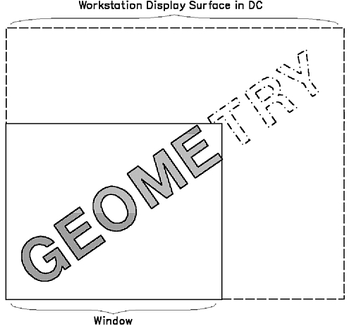