The section on NURBS curves and surface patches includes discussions on the following:
| bgnsurface | |
| Marks the beginning of a NURBS surface definition. | |
| bgntrim | |
| Marks the beginning of a NURBS surface trimming loop. | |
| endsurface | |
| Marks the end of a NURBS surface definition. | |
| endtrim | |
| Marks the end of a NURBS surface trimming loop. | |
| getnurbsproperty | |
| Returns the current value of a trimmed NURBS surfaces display property. | |
| nurbscurve | |
| Controls the shape of a NURBS trimming curve. | |
| nurbssurface | |
| Controls the shape of an untrimmed NURBS surface. | |
| pwlcurve | |
| Describes a piecewise linear trimming curve for NURBS surfaces. | |
| setnurbsproperty | |
| Sets the property for display of trimmed NURBS surfaces. | |
GL provides subroutines that draw parametric non-uniform rational B-spline surfaces (NURBS) that can be trimmed with NURBS curves and piecewise linear curves.
As you can with most other graphics library primitives, you can transform NURBS curves and surfaces with the standard GL modeling commands. You must use the standard lighting models when rendering NURBS curves and surfaces.
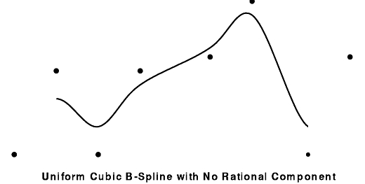
The following figure illustrates a spline with a set of 8 control points. Notice how the spline (or curve) is attracted to the control points, but does not necessarily pass through any of them.
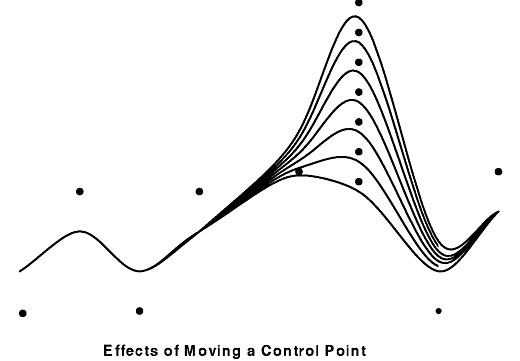
The figure entitled Effects of Moving a Control Point illustrates the result of moving the sixth control point from the left to a series of locations, and the corresponding B-splines created as the one control point moves. Notice that moving the control point affects only a portion of the curve near the control point. This is an important property of B-splines; the influence of the control points is local.
In fact, for cubic B-splines, each small segment of the curve is controlled by the positions of 4 control points. In this example, the curve is actually drawn as 5 small segments. The first is controlled by points 1, 2, 3, 4; the second by 2, 3, 4, 5; and so on.
The last segment is controlled by control points 5, 6, 7, and 8. When the sixth control point is moved, the only parts of the spline affected are those controlled by points 3, 4, 5, 6, points 4, 5, 6, 7, and points 5, 6, 7, 8.
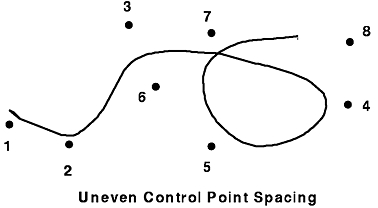
In the two preceding examples, the control points are evenly spaced in the horizontal direction. This is not necessary, as illustrated In the following figure, Uneven Control Point Spacing.
Any number of control points greater than 4 can be used to define a cubic B-spline. The spline is actually drawn in segments, each of which is controlled by successive sets of 4 control points.
Trimmed NURBS surfaces are a convenient means of representing curving, bent, and cut surfaces. The bends and curves of the surface are represented by a polynomial mapping of a 2-D space (the s-t plane, or domain) into 3-D space. A rational polynomial mapping can be achieved in 3-space if the s-t plane is mapped into projective 4-space. Cuts and holes in the surface can be achieved by the use of trimming loops, which are closed curves in s-t space. Trimming loops help describe what subset of the s-t plane should actually be mapped into 3-space (drawn on the monitor). Trimming loops themselves may be specified as NURBS curves or as piecewise linear curves.
To describe an untrimmed NURBS surface, you must specify these controlling factors:
The control points can be either three- or four-dimensional, corresponding respectively to polynomial (sometimes called nonrational) and rational surfaces. In three dimensions, the coordinates have the form (x, y, z), and in four, (wx, wy, wz, w).
Certain dependencies exist between the surface orders, the knot counts, and the number of control points; that is to say, you specify the surface orders and the knot counts in order to obtain the control points. If Os and Ot are the surface orders in the s and t directions, and if Ks and Kt are the knot counts in those directions, then the control points must form a rectangular array of size (Ks - Os)*(Kt - Ot).
You define an untrimmed NURBS surface with the nurbssurface subroutine as shown in this example program:
nurbssurface (
   Int32 sknot_count,   /* of s knots */
   Float64 s_knot[],   /* non-decreasing knot values in s */
   Int32 tknot_count,   /* number of t knots */
   Float64 t_knot[],   /* non-decreasing knot values in t*/
   Int32 s_byte_stride, /* offset to next control point */
            /* in the s direction */
   Int32 t_byte_stride, /* offset to next control point*/
            /* in the t direction */
   double *ctlarray,   /* pointer to first control point */
   Int32 s_order,   /* surface order in s parameter */
   Int32 t_order,   /* surface order in t parameter */
   Int32 type      /* rational or polynomial */
)
This implementation of NURBS surfaces supports up to order 4. Trimming curves can be up to order 8.
Many of the parameters in the preceding example are explained in the following:
The description of control points is somewhat unusual. The s_byte_stride parameter indicates the offset (in bytes) between successive control points in the s direction, and t_byte_stride does the same thing for the t direction. This interface is powerful in that the only requirement is that the x, y, z, and possibly w coordinates are placed in successive memory locations. The data may be a part of a larger data structure, or the points may form part of a larger array. For example, suppose the data appears as follows:
struct ptdata
{
   Int32 tag1, tag2;
   float x, y, z, w;
}   points[5][6];
Then the s_byte_stride parameter should be set to sizeof(struct ptdata) , and the t_byte_stride parameter should be set to 6*sizeof(struct ptdata) , and the ctlarray parameter should be ptdata or &(points[0][0].x) .
As another example, suppose that the data were declared as previously, but only a square of 4 by 4 control points is needed from the middle of the array including everything between and including points[1][1] and points[4][4] . In that case, the s_byte_stride and t_byte_stride parameters are as previously, but the ctlarray parameter is set to &(points[1][1].x) .
Note: In both examples, the type is N_XYZW because the data includes the homogeneous w coordinate.
A trimming curve or trimming loop defines the visible regions in a NURBS surface. You can define trimming curves by the following methods:
In any case, the trimming curve must be closed: that is, the coordinates of the first and last points of the trimming curve must be identical (within a tolerance of 10E-6). Because NURBS curves normally do not pass through the control point, one way to ensure a closed curve is to repeat the coordinates for the control point a number of times equal to the order of the curve. For example, quadruple the control points for a fourth-order curve if you wish to make the curve pass through that point. Another technique is to construct a knot vector that generates positional continuity of the endpoints of the curve.
When error checking is activated, the software sends error messages and does not display the NURBS surfaces associate with the faulty trim data. Likewise, the end points of piecewise linear curves and the NURBS curves used to form a compound trimming curve must touch.
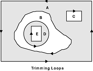
A NURBS surface is the result of a mathematical function that maps domain space to model space. You determine the visible parts of the NURBS surface by defining a trim region. The trim region is the area of the NURBS surface in which the surface domain is trimmed by a closed directed loop (composed of one or more trimming curves) in s-t space, where the interior of the loop is defined to be the region to the left of the loop. The surface domain can be trimmed by many such loops, as long as they describe a consistent region. The loops can neither touch nor intersect (except at their end points, which must touch), and their orientations must also be consistent. The following figure illustrates a set of 5 loops that describe a valid trimming region. The image of the shaded portion is the trimmed NURBS surface.
If no trimming information is provided, the entire surface is drawn. If any trimming loops are given, the outer loop (or loops) must be counterclockwise. Thus to describe a region that consists of the whole surface minus a small circle in the middle, two trimming loops must be specified: one running clockwise around the circle, and another running counterclockwise around the entire s-t domain.
A trimming loop can be described either as piecewise linear curves (a series of s-t coordinates locating successive points along a path), or as NURBS curves in the s-t plane. A loop can be described either by a single NURBS curve, by a piecewise linear curve, or as a series of curves (of either type) joined head to tail.
The general form of the interface to describe a trimmed or untrimmed NURBS surface looks like this:
   bgnsurface();
      nurbssurface(. . .);
   bgntrim();
      nurbscurve(. . .);
   endtrim();
   bgntrim();
      pwlcurve(. . .);
   endtrim();
   bgntrim();
      nurbscurve(. . .);
      pwlcurve(. . .);
      nurbscurve(. . .);
   endtrim();
   endsurface();
Each trimming loop is surrounded by a bgntrim and endtrim subroutine pair. A single curve defines the first two trimming loops; the third loop consists of three segments, connected head to tail. The last point of each curve segment must touch the first point of the next, and the last point of the last segment must touch the first point of the first segment. The nurbssurface subroutine describes the untrimmed surface and appears before any trimming information. The trimmed surface description is bracketed by a bgnsurface and an endsurface subroutine pair.
The other subroutines specifically related to the properties of NURBS surfaces are setnurbsproperty and getnurbsproperty. These subroutines allow the user to set and get drawing tolerances of various types.
All the subroutines in the example, except for the getnurbsproperty subroutine, can be used in display lists. In this implementation, NURBS surfaces described in display lists usually run faster because some of the display computations can be cached between display list traversals.
All the parameters are passed with strict call-by-value semantics. This means that the system copies all values, including trim points and control points, at the time of the call. For example, if you have an array containing control points, and you define a NURBS surface in a display list using it and then change the value in your array, the display list will continue to draw the surface using the original control point values.
The nurbscurve subroutine can be used only within a bgntrim/endtrim loop and in curves of up to order 8.
The structure of the parameters is analogous to those for the nurbssurface subroutine, except, of course, there is only one dimension to describe. When the nurbscurve subroutine describes a trimming curve, it must be two-dimensional, so the only legal values for type are N_STW and N_ST. The control point formats for N_STW and N_ST are (ws, wt, w) and (s, t), respectively.
If a single curve defines the entire trimming loop, both ends of the curve must lie at the same point and must be included in the parameter count.
When you trim a NURBS surface with a NURBS trimming curve, the software analytically calculates coordinates on the surface and their corresponding normal vectors for each point on the tessellated NURBS trimming curve.
nurbscurve (
Int32 knot_count,   /* number of knots */
Float64 knot_list[],   /* non-decreasing knot sequence */
Int32 stride,      /* byte offset to next control point */
Float32 *ctlarray,   /* pointer to first control point */
Int32 order,      /* spline order */
Int32 type      /* spline type -- 2D, 3D, rational,
            polynomial */
)
To define a piecewise linear trimming curve, use the pwlcurve subroutine. The syntax is as follows:
void pwlcurve(Int32 count, Float64 *data_array,
              Int32 stride, Int32 type)
The trimming curve in the s-t plane is drawn by connecting each point in the data_array parameter to the next. It is as important to increment the trim point count as it is to duplicate the last point. In other words, although the last and first points are identical, they must be specified and counted twice.
The following subroutines control NURBS curves and surfaces display properties.
The setnurbsproperty subroutine changes various properties that control the rendering of NURBS curves and surfaces. The call uses this format:
void setnurbsproperty(Int32 property, Float32 value)
A list of properties is defined in the /usr/include/gl/gl.h file and includes N_PIXEL_TOLERANCE and N_ERRORCHECKING. Each has some reasonable default value but can be changed to affect the accuracy of some part of the rendering. You can get the current value of any of these properties with a call to the getnurbsproperty subroutine. The syntax is as follows:
void getnurbsproperty(Int32 property, Float32 *value)
For maximum generality, express the value of a property in floating point. For some properties, only integer values make sense, but you must still pass them in floating-point form; for example, 1.0 means TRUE.
The values of the properties are global to a process, and each call to the setnurbsproperty subroutine changes this global state.
The properties have the following meanings:
| N_PIXEL_TOLERANCE | A value representing how accurately a NURBS surface is to be rendered. Smaller values indicate more accuracy. |
| ERRORCHECKING | If TRUE, performs additional error checking. |