The easiest way to configure the X.25 software is through SMIT. When you are configuring the system, options are presented based on what adapters are available in the system.
Note: It is best if all the adapters to be used are installed in the system before the X.25 configuration is begun. Adapters can be added or deleted at a later time, but for the instance numbers to be kept in a simple order, as much of the configuration as possible should be done at one time.
The main areas of configuration are:
From a system where the adapters are installed, the following steps outline those necessary to configure X.25 ports ready for use:
The X.25 software is configured based on the adapter it is to run on. To reach the communication devices screen:
Under the communication devices list are entries for the adapters supported in the system. Select the adapter type required and a list of the available software packages for that adapter type is listed. Depending on the adapter, select one of the following:
Note: After you select IBM 2-Port Multiprotocol PCI Adapter do the following:
- Select Manage HDLC Device Driver
- Select Manage Additional Protocols / Emulators
- Select Manage X.25 over HDLC Device Driver
The screen shown in the following figure allows the instances of the twd device driver to be managed. If a driver is in the defined state, Configure a Defined Device Driver makes it available, assuming that no other driver is configured at the adapter. The device driver is added to an adapter before the X.25 ports on that adapter are added, and is removed after all the X.25 ports on the adapter are removed.
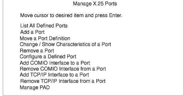
Select Manage X.25 Ports to manage the X.25 ports on the system, from the Licensed Program's initial SMIT screen. This brings up the Manage X.25 Ports SMIT screen as shown in the following figure.
From the Manage X.25 Ports SMIT screen, the following actions can be taken:
To add a port, select Add Port and a list of the available adapters will be presented. When you select an adapter, a SMIT screen will allow entry of the port's NUA. Information on the attribute choices available is given in the help text. It is probable that the port will require further configuration before use to match its characteristics with those provided by the network provider. Use the Change/Show Characteristics of Port screen to alter the attributes.
The following attributes must be entered:
The following attributes are optional. See "General Parameters" for more details.
The attributes defining a port can be transferred to a different port. When Move Port Definition is selected:
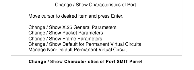
From the "Manage X.25 Ports" SMIT screen, select Change/Show Characteristics of Port. The attributes for the port are divided into a number of categories. They are listed in the SMIT screen in the order in which they will most likely be used (see the Change/Show Characteristics of Port SMIT Panel figure). It is often not necessary to configure anything other than the port's general parameters.
General parameters are those most likely to need configuring. For a given port, there are the following attributes:
| NUA | The network user address for the port. This is usually supplied by the network provider and must agree with the subscription obtained. |
| Calling address | On a few networks, the NUA of the machine originating the call cannot be put into the call it generates. Usually the calling address is allowed. This attribute is used only with COMIO connections. |
| Enable DLPI | If direct access to the frame layer is required on this port, then DLPI should be enabled. This disables packet layer (X.25) access. DLPI is usually disabled. |
| VC ranges | VC ranges are constructed according to the lowest logical channel number and the logical channels desired for each of the VC types. The lowest logical channel number indicates the lowest-numbered logical channel that may be used for a specific VC type. This number depends on the network subscription and must be in the range of 1 through 4096. The lowest logical channel may be 0 only when the VC type is not used. Logical channel number 0 may not be used for a VC channel because it is always used as the network protocol channel. Check with your network provider to learn if logical channel 0 is included in a VC range.
The number of logical channels indicates how many VCs to configure starting at the lowest logical number of that VC type. This information is supplied by the network provider. The specified VC channel ranges must not overlap and must not exceed the total number of channels allowed. In addition, the logical channel numbers must be defined according to the following rule: PVC < Incoming SVC < Two-way SVC < Out-going SVC If the range of VCs is not needed, set the lowest logical channel number and the number of logical channels for the VC type to 0. |
| X.32 | This set of attributes should be set if the network provider requires X.32 DTE identification. Both the X.32 XID identity and the X.32 XID signature are supplied by the network provider. For more information, refer to "Configuring a Port for X.32". |
| Dial-Up | These attributes must be set if a dial-up connection is used. For more information, refer to "Dial-Up Parameter Descriptions" |
Packet parameters give the characteristics of the packet layer.
The frame parameters give the characteristics of the frame layer.
| T (timers) | The T1 timer gives the timeout by which an acknowledgement of the data sent should have been received. On slow lines, especially with large data packets, the value of T1 should not be too low. If too low, the frame will not be fully transmitted before the timer expires, and so a high number of T1 expirations would be seen. N2 specifies, if T1 does timeout, how many times the frame should be retransmitted. T2 is less likely to be varied, specifying to the software the required turn around time for a frame. T3 and T4 ensure that any frame layer failure is recognized. |
| Frame modulo | Specifies whether the counters that check frame-layer activity between the DTE and the DCE work in modulo 8 or 128. Usually modulo8 is used. This value will be based on the network. |
| Frame window | This gives the number of frames that can be sent to the DCE before the DTE must wait for acknowledgement. The value, typically, does not affect performance greatly and should be based on the network providers' recommendation. |
| DTE/DCE | Selection on whether the system operates as DTE or DCE can be made at the packet or frame layers. This selection can be automatic (based on the ISO standard ISO8208) or fixed. However, this does not allow the system to act as a full DCE. |
| Connection mode | Once the physical layer is connected, the frame layer is established. The different networks require different modes of startup at the frame layer. One of the most common is for the DTE to start sending out SABM frames to indicate its frame layer is ready. The network provider will provide additional information in this area. |
The characteristics of a PVC cannot be changed at the time of usage. Unlike SVCs, they have no call request/confirm exchange in which to negotiate packet size. The X.25 Default PVC Parameters SMIT screen allows the defaults that are to be assumed for this port to be set. If a specific PVC does not match these defaults, then this should be given as a non-default PVC. The Manage Non-Default PVC screen is provided for this. As identification of a given PVC is based on its logical channel number, this must be specified when dealing with non-default PVCs.
| Packet sizes | The packet sizes to be used. |
| Window sizes | The packet window sizes to be used. |
| D bit | If the applications being run require DTE-to-DTE data acknowledgement, they make use of the D bit. On some networks, this is a separate option, and so may not be subscribed to. If this is the case, then D bits should not be allowed. Usually, D bits should be allowed. |
The CCITT V.25bis Recommendation provides a protocol to connect automatic calling and/or answering equipment to a telephone network. This recommendation contains two types of connections. The connection type is distinguished by the DTR signal used. If the DTR signal is 108.1, the connection type is called direct. A direct V.25bis connection uses only V.24 signals to establish connections. If the DTR signal is 108.2, the connection type is called addressed. An addressed connection uses V.25bis commands and V.24 signals to establish connections. To use the addressed mode, your modem or ACU must support the V.25bis command set.
The V.25bis functionality provided in the Streams X.25 LPP configures the port for both incoming and outgoing calls. Therefore, your port can both originate and answer calls without having to be reconfigured.
Use the following method to configure a port for V.25bis dialing.
Using SMIT, enter:
smit
Select Change/Show Characteristics of Port.
Select Change/Show X.25 General Parameters.
On the Change/Show X.25 General Parameters screen, there is a Dial-Up Configuration menu that displays certain options for setting up calls.
The setup in the SMIT menus must match the setup of the actual modem or autocall unit (ACU) you are using. Therefore, it is important that you are familiar with the modem setup before you attempt to configure the port for V.25bis.
Here is a sample setup for using V25bis addressed mode. A phone number must be specified if the port is to originate any calls. When originating a call, the X.25 adapter sends the dial string included in the Phone Number or Address to Call field to the modem or ACU using V25bis commands.
Dial-Up Configuration
**********************
Connection type                           [V25bis]        +
V25bis Call Establishment Method          [Addressed]     +
Phone Number or Address to Call           [5551234]
Maximum Connection Delay                  [30]            #
Enable/Disable DSR Polling                [enable]        +
DSR polling timeout                       [30]
Here is a sample setup for using V25bis direct mode:
Dial-Up Configuration
**********************
Connection type                           [V25bis]         +
V25bis Call Establishment Method          [Direct]         +
Phone Number or Address to Call           []
Maximum Connection Delay                  [30]             #
Enable/Disable DSR Polling                [enable]         +
DSR polling timeout                       [30]
| Connection Type | There are three types of connections:
| ||||||||||||||
| V25bis Call Establishment Methods | There are two V25bis call establishment methods:
| ||||||||||||||
| Phone Number or Address to Call | Specifies the phone number the modem should call to establish a connection. The phone number may contain the digits 0 through 9 inclusive and any of the following dial modifiers:
| ||||||||||||||
| Maximum Connection Delay | Maximum time in seconds to allow for connection establishment. Must be set long enough for modems to perform handshaking or training operations. When originating calls, this value should be smaller than the T3 idle timer frame-layer parameter. Used for all dial-up connections. For leased connections, this value remains unchanged. | ||||||||||||||
| Enable/Disable DSR Polling | DSR polling must be enabled if using a V25bis or manual-dial dial-up connection. If using a leased connection, DSR polling must be disabled. | ||||||||||||||
| DSR Polling Timeout | After call establishment, time in seconds to wait after DSR has dropped before ending the connection. Used only if DSR polling is enabled. |
Use the following method to configure a port to use X.32 XID authentication.
smit
Select Change/Show Characteristics of Port.
Select Change/Show X.25 General Parameters.
On the Change/Show General Parameters screen, the settings for the X.32 attributes must be obtained from your network provider.
| Use X.32 XID Exchange | Indicates whether or not to use X.32 XID authentication procedures when the link is established. |
| X.32 XID Identity | Represents the X.32 identity of your port. This attribute must be provided by the DCE you are calling. The identity should be a string of 64 hexadecimal characters. |
| X.32 Signature | Identifies your password. This attribute must be provided by the DCE you are calling. The signature should be a string of 64 hexadecimal characters. |
From the Manage X.25 Ports SMIT screen, emulation of the AIX Version 3 base X.25 driver support can be added to an X.25 port. This screen also allows it to be removed. For details on this screen, see "Managing Ports".
When Add COMIO Interface to Port is selected, a choice of available ports is presented. Only one emulator can be added to any one port, and if it has already been added to the port chosen, the operation will fail.
When Remove COMIO Interface from Port is selected, a choice of the emulators configured on the system is presented.
Note: On AIX Version 3, the base X.25 support produces COMIO device-specific files with the same names as the X.25/6000 Licensed Program. The instance numbers of the ports are unique, but the two types of ports cannot be distinguished by their names. See the lsx25 command for details on how to distinguish the two types.
TCP/IP support can be added or removed from a given port. For more details of the TCP/IP support, refer to the section on TCP/IP in the AIX Version 4.3 System Management Guide: Communications and Networks.
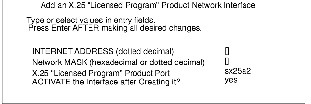
To add TCP/IP support, select Add TCP/IP Interface to Port from the Manage X.25 Ports screen and select the correct adapter. The following Add an X.25 "Licensed Program" Product Network Interface screen displays:
| Internet Address | The IP address to be given to this interface, for example, 192.35.231.224. There should be a host name for this address in /etc/hosts. |
| Network Mask | The netmask of the network depends on the network's implementation. If the IP connection is simply from this port to another, then the default, which is obtained by leaving the field blank, is usually acceptable. If many X.25/IP connections are being used to make up a network, the netmask should be consistent across the systems. |
| "Licensed Program" Product Port | The X.25 port selected. |
| Activate | Choose whether to immediately activate the interface or not. If there is still configuration work to be done on the port, then it should be activated later with the ifconfig command. |
To remove a TCP/IP interface from a port, select Remove TCP/IP Interface from Port and then choose the interface to be deleted.
Note: Use ifconfig down instead of ifconfig detach for STREAMS-based X.25 in AIX Version 3. This does not apply to Version 4 users.
AIX Version 3.2 conforms to RFC 1236 "IP to X.121 Address Mapping for DDN" which defines an algorithm that automatically determines the NUA based on the Internet address.
Choosing the DDN network identifier invokes this algorithm in place of the x25ip tables. The RFC defines this support for Class A Internet addresses only (Class B and C addresses are also supported).
For all other types of network, the x25ip table maps TCP/IP Internet addressing to the X.121 Network User Address (NUA). This table is maintained via the SMIT IP/X.25 Host Entry menu.
Create an entry in this table for each remote host using either of the following methods:
smit mkx25s
smitChoose the following SMIT menus:
Select Communications, Applications, and Services.
Select Network Interface Selection.
Select X.25 "Licensed Program" Product IP Host Configuration.
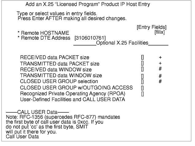
Select Add an X.25 "Licensed Program" Product IP Host Entry.
Select Add a Switched Virtual Circuit (SVC) X.25 "Licensed Program" Product IP Host Entry.
Both of these methods display the Add an X.25 "Licensed Program" Product IP Host Entry screen. This screen contains fields in which you type or select the desired values. The following figure shows the entry fields with sample field values:
Notes:
- A virtual call is made when the first session with a remote system is established.
- Several IP sessions can share the same virtual circuit. Once an X.25 communication has been established, all IP traffic between two systems shares the same virtual circuit. Only one SVC or PVC is needed for communications between two systems.
- The X.25 virtual circuit is left connected for a period of time after the last IP session has been closed. This is so the cost of call establishment is not incurred if the remote system is contacted again in the near future (which is reasonable). This time delay, which is approximately 20 minutes, is modifiable with the Network Options (no) command using the arpt_killc option. The no command is available to modify some network parameters for the pending IPL. If you want your new values to remain unchanged after each system boot, add the command at the end of the /etc/rc.tcpip file. For example, to clear the virtual circuit after five minutes of inactivity:
no -o arpt_killc=5Note: This applies to SVCs and PVCs that are removed using the arp -d command.- To clear a TCP/IP X.25 virtual connection, use the arp -d command. For example to clear an existing virtual connection between kilix and filix , type on filix:
arp -d filix
The functionality of the PAD can be divided into two types of PAD, host and terminal PADs. The host PAD allows remote ASCII terminals to access applications running on it, with their access across an X.25 network. A terminal PAD allows the ASCII terminals to directly attach to the system over asynchronous links, and for them to use the X.28 protocol to establish calls with the remote X.25 attached system.
To enable host PAD support, the Manage Triple-X PAD option should be selected from the Manage X.25 Device Driver menu. This option brings up a menu from which the host PAD support can be added or stopped - the Start/Stop the Triple-X PAD X.29 Daemon menu. Select the Add and Configure/Stop the X.29 Daemon menu to start the X.29 daemon. The daemon is only started for that instance and will be stopped automatically if the machine is rebooted. To avoid having to restart the daemon each time, add the following to any start-up script:
/usr/lib/drivers/pse/x29d
The terminal support does not need to be configured and is available once the X.25 and PAD software is installed, and the X.25 ports configured.