This chapter provides information on asynchronous communication standards, hardware, terminology, and concepts used throughout this book.
To understand serial ports, consider:
Serial ports are used to physically connect asynchronous devices to a computer. They are located on the back of the system unit, using the multiport adapter, such as, the 8-, 16-, 64- and 128-port asynchronous adapters and the 7318 terminal servers.
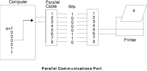
To understand the functionality of a serial port, it is necessary to first examine the parallel communications. A standard parallel port uses eight pins, or wires, to simultaneously transmit the data bits, making up a single character. The following figure shows the parallel transmission of the letter a .
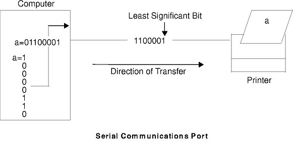
Serial ports require only a single pin, or wire, to send the same data character to the device. To accomplish this, the data is converted from a parallel form (sent by the computer), to a sequential form, where bits are organized one after the other in a series. The data is then transmitted to the device with the least significant bit (or zero-bit) sent first. Once received by the remote device, the data is converted back into parallel form. The following figure shows the serial transmission of the letter a .
Serial transmissions of a single character are simple and straight forward; however, complications arise when a large number of characters are transmitted in series as shown in the following figure. The receiving system does not know where one character ends and the other begins. To solve this problem, both ends of the communication link must be synchronized or timed.
Synchronization is the process of timing the serial transmission to properly identify the data being sent. The two most common modes are synchronous and asynchronous.
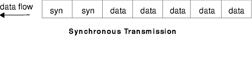
The term synchronous is used to describe a continuous and consistent timed transfer of data blocks. These types of connections are used when large amounts of data must be transferred very quickly from one location to the other. The speed of the synchronous connection is attained by transferring data in large blocks instead of individual characters.
The data blocks are grouped and spaced in regular intervals and are preceded by special characters called syn or synchronous idle characters. See the following figure.
Once the syn characters are received by the remote device, they are decoded and used to synchronize the connection. Once the connection is correctly synchronized, data transmission may begin.
An analogy of this type of connection would be the transmission of a large text document. Before the document is transferred across the synchronous line, it is first broken into blocks of sentences or paragraphs. The blocks are then sent over the communication link to the remote site. With other transmission modes, the text is organized into long strings of letters (or characters) that make up the words within the sentences and paragraphs. These characters are sent over the communication link one at a time and reassembled at the remote location.
The timing needed for synchronous connections is obtained from the devices located on the communication link. All devices on the synchronous link must be set to the same clocking.
The following is a list of characteristics specific to synchronous communication:
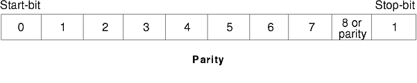
The term asynchronous is used to describe the process where transmitted data is encoded with start and stop bits, specifying the beginning and end of each character as shown in the following figure.
These additional bits provide the timing or synchronization for the connection by indicating when a complete character has been sent or received; thus, timing for each character begins with the start bit and ends with the stop bit.
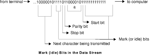
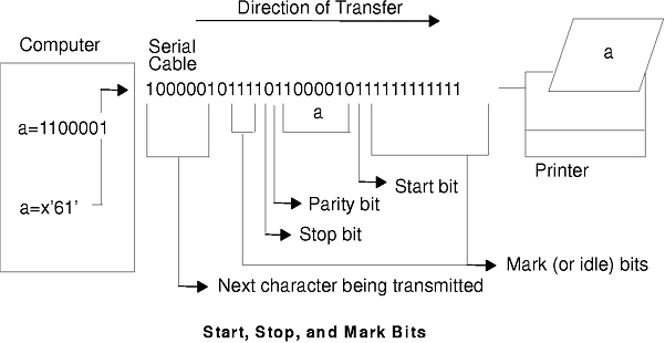
When gaps appear between character transmissions, the asynchronous line is said to be in a mark state. A mark is a binary 1 (or negative voltage) that is sent during periods of inactivity on the line as shown in the following figure.
When the mark state is interrupted by a positive voltage (a binary 0), the receiving system knows that data characters are going to follow. It is for this reason that the start bit, which precedes the data character, is always a space bit (binary 0) and that the stop bit, which signals the end of a character, is always a mark bit (binary 1).
The following is a list of characteristics specific to asynchronous communication:
The following describes the parameters used during serial communication.
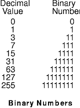
The number of bits-per-character (bpc) indicates the number of bits used to represent a single data character during serial communication. This number does not reflect the total amount of parity, stop, or start bits included with the character. Two possible settings for bpc are 7 and 8.
When using the seven bits-per-character setting, it is possible to only send the first 128 characters (0-127) of the Standard ASCII character set. Each of these characters is represented by seven data bits. The eight bits-per-character setting must be used to send the ASCII Extended character set (128-255). Each of these characters may only be represented using eight data bits. Refer to the Binary Numbers figure for a graphic representation.
Bits-per-second (bps) is the number of data bits (binary 1s and 0s) that are transmitted per second over the communication line.
The baud rate is the number of times per second a serial communication signal changes states; a state being either a voltage level, a frequency, or a frequency phase angle. If the signal changes once for each data bit, then one bps is equal to one baud. For example, a 300 baud modem changes its states 300 times a second.
The parity bit, unlike the start and stop bits, is an optional parameter, used in serial communications to determine if the data character being transmitted is correctly received by the remote device.
The parity bit can have one of the following five specifications:
Most modern serial communications devices (modems, terminals, etc.) use a 10-bit transmission character:
     1  bit  for the start bit
7 or 8  bits for the data character
1 or 0  bits for the parity setting
2 or 1  bits for the stop bits
----------------------------------
    10  bits for total character transmission.
If the number of data bits is set to eight:
8 bpc + 1 start +1 stop + 0 parity = 10 bits
there are no bit positions left for parity; therefore, parity must be set to none.
If the number of data bits is set to seven, parity can be even, odd, or none.
7 bpc + 1 start + 1 stop + 1 parity = 10 bits
Another alternative is having parity set to none and stop bits set to two (this is rarely used).
7 bpc + 1 start + 2 stop + 0 parity = 10 bits.
If the parity bit is used for error detection on a communication line, both the sending and receiving systems must be configured identically to avoid possible problems during transmissions.
The start and stop bits are used in asynchronous communication as a means of timing or synchronizing the data characters being transmitted. Without the use of these bits, the sending and receiving systems will not know where one character ends and another begins.
Another bit used to separate data characters during transmission is the mark (or idle)RS bit. This bit, a binary 1, is transmitted when the communication line is idle and no characters are being sent or received. When a start bit (binary 0) is received by the system, it knows that character data bits will follow until a stop bit (binary 1) is received. See the following figure.
The EIA 232D standard was developed in 1969 to specify the connections between a computer and a modem. The term itself is an acronym which can be read as follows:
Electronics Industry Association (EIA) accepted standard, ID number 232 revision D.
EIA 232D specifies the characteristics of the physical and electrical connections between two devices. Names and abbreviations are assigned to each pin or wire necessary for serial communications, for example:
| Signal | Symbol | Pin |
| Transmit Data | TxD | 2 |
| Receive Data | RxD | 3 |
| Request to Send | RTS | 4 |
| Clear to Send | CTS | 5 |
| Data Set Ready | DSR | 6 |
| Signal Ground | SG | 7 |
| Carrier Detected | CD | 8 |
| Data Terminal Ready | DTR | 20 |
| Ring Indicator | RI | 22 |
In EIA 232D, devices using pin 2 (TxD) for output (for example, computers and terminals) are given the name data terminal equipment (DTE). Devices using pin 2 (TxD) for input (for example, modems) are given the name data communication equipment (DCE).
EIA 232D also specifies the connectors. A DTE device normally has male connectors while DCE devices have female connectors. This standard is not always adhered to by manufacturers; therefore users should always review the device documentation before cable connection.
Simplex, or one-way communication, is the simplest connection form between two devices. This mode of communication allows data to be transmitted in only one direction and requires only two lines be connected, for example, TxD (or RxD) and SG.
There are two forms of two-way communications: half-duplex and full-duplex. A connection in half-duplex mode allows data to be transmitted in two directions but not simultaneously. An analogy of half-duplex would be the use of a CB-radio where two-way communication is possible but only one person can speak at a time.
In full-duplex, or duplex mode, data communication can take place in two directions simultaneously. An analogy for full-duplex is a telephone conversation when both persons are talking at the same time.
Serial devices, such as printers and modems, do not process data as quickly or efficiently as the computers they are connected to. Some type of data flow control is needed by the serial device to limit the amount of data transmitted by the system.
The term flow control is used to describe the method in which a serial device controls the amount of data being transmitted to itself. The three types of flow control discussed in this section are:
Ready to send/clear to send (RTS/CTS) is sometimes called pacing or hardware handshaking instead of flow control. The term hardware handshaking comes from the use of cabling and voltages as a method of data transmission control. Unlike XON/XOFF, which sends control characters in the data stream, RTS/CTS uses positive and negative voltages along dedicated pins or wires in the device cabling.
A positive voltage means data transmission is allowed while a negative voltage signifies that data transmission should be suspended.
Data terminal ready (DTR), another form of hardware flow control, is normally generated by the devices, such as printers to indicate that they are ready to communicate with the system. This signal is used in conjunction with data set ready (DSR) generated by the system to control data flow.
A positive voltage means data transmission is allowed while a negative voltage signifies that data transmission should be suspended.
Transmitter on/transmitter off (XON/XOFF) flow controls involves the sending of data transmission control characters along the data stream (TxD and RxD). For this reason it is referred to as software flow control.
When data is sent to a modem, it is placed in a buffer. Just before that buffer reaches its maximum capacity, the modem will send an XOFF character to the system and the system will stop transmitting the data. When the modem's buffer is almost empty and ready for more data, it will send an XON character back to the system causing more data to be sent.
Modems attached to the server operating at a speed of 9600 or above are recommended to use RTS/CTS hardware handshaking instead of XON/XOFF flow control. This will avoid buffer overrun in a system with limited resources. RTS is not a default value on any tty port and must be set by the system administrator accordingly.
AIX Version 3.2.5 provides the following methods of adding RTS to the tty port:
Direct tty# -Any direct
Stack information for a tty on the native S1 port should resemble:
rs, dtropen, rts, xon, posix
Use the following C code to add RTS to a tty port on an AIX 3.2 system. To make the program more permanent, insert the file name of the compiled version (complete with path) at the end of your /etc/rc file and the changes will take effect again at next reboot. This is necessary because RTS is removed from the tty stack after a reboot.
/* C Program to add RTS discipline to tty port(s).

NOTE: This program is supplied "as is" and is NOT supported by
IBM. It is intended as an aid to administrators only.
To create: vi addrts.c <enter> To compile: cc -o addrts addrts.c
/**************************************************************
                        Program starts now
************************************************************** */
#include <stdio.h>
#include <fcntl.h>
#include <termios.h>
#include <sys/tty.h> main()
{
   int fd;
   fd = open("/dev/tty0", O_NDELAY|O_RDWR);
   ioctl(fd, TXADDCD, "rts");
   /* adds rts to tty0 */
   close(fd);
}
/****************************************************************
                         Program ends now
 ************************************************************* */
To enable RTS/CTS for a port in AIX Version 4, use the following steps: