Pentium Processor Upgrade
SEC 2 ; PowerLeap
Interposer
Draft # 1. 2002.11.04
Draft # 2. 2002.11.16
Updated 2002.12.02
Updated 2002.12.13
For those who are planning to use AMD K6-II CPU rated higher than 350MHz
for your system running Windows 95B or 95C, you need amdk6upd.exe
.
PL-OD54C
Upgrade for P-75/90/100 systems to P-133 to P-200 ( Non-MMX Upgrade).
Voltage regulator is not used. This interposer provides clock
multiplying jumpers for BF1 which is omitted in P-75/P-90 systems.
Very simple and easy to use . Actually speaking you don't need this
interposer for
upfgrading P-75/P-90 to classic Pentium 133-200, if you don't
care for soldering rework of a planar.
Check Peter's
Blue Book page for the method.
This one can be used for P-90 Y complex.
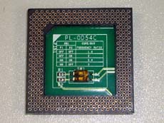 |
SW SETTING
|
SW1
|
CORE/BUS
FREQUENCY RATIO
|
|
P1
|
P2
|
|
OFF
|
OFF
|
1.5 x
|
|
OFF
|
ON
|
2.0 x
|
|
ON
|
ON
|
2.5 x
|
|
ON
|
OFF
|
3.0 x
|
|
|
|
P1 connected to BF1 ( Pin X34 )
P2 connected to BF0 ( Pin Y33 ) |
|
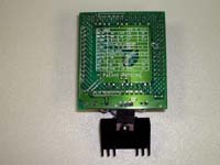
PL-MMX
VER.2.01V
Upgrade for Pentium 75-200 to MMX Pentium, K6 and M2.
Available CORE VCC; 3.3V, 3.1V, 2.8V , 2.1V
Maximum CORE/BUS ratio is 3.5 x ( MMX233 & K6-2333 )
I got this unit very cheep planing to use it for 8640. Back in home,
pulled off the outer case of Server 320, set a K6-233 onto the interposer
securely and attempted to place it onto the socket on the planar....A huge
heat sink sit in front of CPU sockets BLOCKED
the interposer.
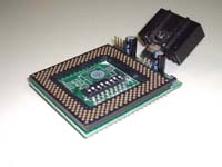
For P-90 Ycomplex, you have to rearrange fins of LT11084 heatsink so
that you can set the interposer on the socket properly.
This unit looks like with an Evergreen's CPU adapter introduced
in Tam's page.
When I got Server 500, This one could have it's home for a while. Yes,
just for a while.
I bent two of the pins when I pushed it onto the socket while I tested
CPUs including MMX 233. One of the bent pin was finally torn
off when I tried to straighten it. Grrr..... Broken Arrow, that's
it.
Compatibility ( physically fits or not )
| PC Server 320 8640-Mxx |
No |
| Type 4 Y ( P-90 complex ) |
Yes ( rewrk needed ) |
| PC750 6885/5886 |
|
 |
 |
|
|
|
|
|
| SW1:P1 |
OFF |
OFF |
ON |
ON |
| SW1:P2 |
OFF |
ON |
OFF |
ON |
| RATIO |
3.5/1.5 |
3
|
2
|
2.5
|
| CPU |
P55C, M2, K6 ( P54C, K5 )
|
| RATIO |
3
|
3
|
2
|
2
|
| CPU |
6X86, 6X86L
|
|
|
|
|
|
| CLK VCC |
Socket 5 5V |
Socket 7 3.3V |
| SW1: P4 |
ON |
OFF |
|
|
|
|
|
| CORE VCC |
3.3V |
3.1V |
2.8V |
2.5V |
| SW1: |
P5 |
P6 |
P7 |
P8 |
| CPU |
P54C |
K6 *1 |
P55C |
M2 |
*1 Some of K6-233 are rated 2.2V
VCC |
 |
|
PL-ProMMX
( SVRAM ) Ver.4.0
Older version
It looks like PL-ProMMX
Plus ( below ) . Two capacitors are placed around Pin 1 ( front edge
) but the swich block
is placed inside the sockt at CPU side like PL-MMX
listed above.
Compatibility ( physically fits or not )
| PC Server 320 8640-Mxx |
Yes for main socket, Not good
for 2nd socket |
| Type 4 Y ( P-90 complex ) |
Rework needed. Not recomendable. |
| PC750 6885/5886 |
Yes |
Newer
Version now listed in Powerleap website.
Looks like PL-ProMMX Plus Ver 4.0.
No capaciors at the front edge but the switch block locates at CPU side.
I don't have this model. It may fit to PCServer 320 both for
main and 2nd socket, P-90 complex, PC750 and other
clone like IBM PCs.
PL-ProMMX
Plus ( older version )
Upgrade for Pentium 75-200 to Intel MMX233 and ( upto ) K6-2/366.
Covers Core Vcc from 1.6V to 3.5V with 0.1V stepping.
JP2, Jumper blocks for Core Vcc setting, and a can type capacitor
locates in front of Pin 1. Overhang of PCB for these parts
hits the Voltage regulator in front of 2nd
CPU socket of 8640/MCA planar.
NO, it does not fit to 8640-MYR.
It doesn't fit to the
2nd CPU socket but DOES fit to the 1st socket.
It can be used for PC750 too.
Compatibility ( physically fits or not )
| PC Server 320 8640-Mxx |
Yes for main socket, Not good
for 2nd socket |
| Type 4 Y ( P-90 complex ) |
Rework needed. Not recomendable. |
| PC750 6885/5886 |
Yes |
JP1 Settings: Clock Multiplier
|
P55C, K6, K6-2, 6x86L, 6X86MX, MII( Dual Volt ),
C6, P54C( Single Volt ) |
6X86 *2 |
| CLKMUL |
6 x *1
|
5.5 x
|
5 x
|
4.5 x
|
4 x
|
3.5 x
|
3 x
|
2.5 x
|
2 x
|
| Pin 1-2 |
Closed
|
Open
|
Open
|
Closed
|
Closed
|
Open
|
Open
|
Closed
|
Closed
|
| Pin 3-4 |
Open
|
Open
|
Closed
|
Closed
|
Open
|
Open
|
Closed
|
Closed
|
Open
|
| Pin 5-6 |
Open
|
Closed
|
Closed
|
Closed
|
Closed
|
Open
|
Open
|
Open
|
Open
|
*1: 6x setting is not listed in the installation guide.
*2: For 6x86( Single-Voltage ) and 6X86L ( Dual Voltage
)
JP2 Settings: CPU Voltage and Overheating Protection
|
|
|
|
|
|
|
|
| Core Voltage |
3.5V
|
3.3V
|
3.2V
|
2.9V
|
2.8V
|
2.2V
|
1.8V
|
| CPU Type |
C6
WinChip
|
P54C
|
K6-233 *1
|
K6-200
6x86MX
|
P55C
6X86L
|
K6-266/300
K6-2
|
K6-3 *2
|
| JP2: Pins 1-2 |
Closed
|
Closed
|
Open
|
Closed
|
Open
|
Open
|
Closed
|
| JP2: Pins 3-4 |
Closed
|
Open
|
Open
|
Open
|
Open
|
Closed
|
Closed
|
| JP2: Pins 5-6 |
Closed
|
Closed
|
Closed
|
Open
|
Open
|
Open
|
Open
|
| JP2: Pins 7-8 |
Closed
|
Closed
|
Closed
|
Closed
|
Closed
|
OPen
|
Open
|
| JP2: Pins 9-10 |
Closed
|
Closed
|
Closed
|
Closed
|
Closed
|
Closed
|
Open
|
*1 Check carefully actual voltage printed on the Chip.
Some are rated 3.2V and the others are rated
2.2V.
*2 K6-3 is listed in the guide book. I myself have
not yet tested K6-3 with this interposer.
Pins 11-12: CPU Overheating Protection)
| JP2: Pins 11-12 |
Overheating Protection
|
|
Closed
|
Enabled
|
|
Open
|
Disabled
|
PL-ProMMX
Plus Ver. 4.0 ( Current model )
Attention : Current product of this model is sold as
PL-ProMMX Plus. You 'd better check how it looks like if you
are planning to use it for Type 4 Y P-90 complex. Older version with
exactly the same name may not fit to Type-4 P-90 complex. The Latest
model is sold with a heat sick/fan combo which is different from the one
pictured below.
Upgrade for Pentium 75-200 to Intel MMX233 and K6-2/400-450.
Wide variation for CORE VCC. Covers most of intel,
AMD ( except K6-III ), IBM/Cyrix and IDT CPUs.
This one can be used for PC Server 320 8640
( both for 1st and 2nd socket), Y complex and PC750 6885/6886
. No capacitor nor jumper block locates in front of Pin
1( front-end of the PCB ), thus the interposer will not meddle with
a heat sink of a 320 planar or Y complex.
Compatibility ( physically fits or not )
| PC Server 320 8640-Mxx |
Yes for both main and 2nd socket |
| Type 4 Y ( P-90 complex ) |
Yes |
| PC750 6885/5886 |
Yes |
SW1 Setting
SW1: Pins 1,2 & 3 for Clock Multiplier
|
P55C, K6, K6-2, 6X86MX, MII( Dual Volt ), C6, WinChip2,
P54C( Single Volt ) |
6X86 *1 |
| CLKMUL |
6 x
|
5.5 x
|
5 x
|
4.5 x
|
4 x
|
3.5 x
|
3 x
|
2.5 x
|
2 x
|
| Pin 1 |
ON
|
OFF
|
OFF
|
ON
|
ON
|
OFF
|
OFF
|
ON
|
ON
|
| Pin 2 |
OFF
|
OFF
|
ON
|
ON
|
OFF
|
OFF
|
ON
|
ON
|
OFF
|
| Pin 2 |
OFF
|
ON
|
ON
|
ON
|
ON
|
OFF
|
OFF
|
OFF
|
OFF
|
SW1: Pins 4, 5, 6, 7 & 8 ( Core Voltage )
|
|
|
|
|
|
|
|
| Core Voltage |
3.5V
|
3.3V
|
3.2V
|
2.9V
|
2.8V
|
2.4V
|
2.2V
|
| CPU Type |
C6
WinChip
|
P54C
6X86
|
K6-233 *
|
K6-200
6x86MX
MII
|
P55C
6X86L
|
K6-2/450
|
K6-266
K6-300
K6-2
|
| SW1: Pin 4 |
ON
|
ON
|
OFF
|
ON
|
OFF
|
OFF
|
OFF
|
| SW1: Pin 5 |
ON
|
OFF
|
OFF
|
OFF
|
OFF
|
OFF
|
ON
|
| SW1: Pin 6 |
ON
|
ON
|
ON
|
OFF
|
OFF
|
ON
|
OFF
|
| SW1: Pin 7 |
ON
|
ON
|
ON
|
ON
|
ON
|
OFF
|
OFF
|
| SW1: Pin 8 |
OFF
|
OFF
|
OFF
|
OFF
|
OFF
|
OFF
|
OFF
|
* Check carefully actual voltage printed on the CPU label.
( there are two types in K6-233, different core Vcc )
* You can set Core Voltage to another value not listed in above diagram.
From 1.30 V to 2.00V by 0.05V stepping and from 2.0V to 3.5V
by 0.1V stepping.
SW1: Pin 10 ( CPU Overheating Protection )
| SW1: Pin10 |
Overheating Protection
|
|
ON
|
Enabled
|
|
OFF
|
Disabled
|
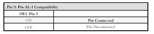
SW1:Pin 9
No comment for Pin 9 in the associated Manual . But there is
a instruction for this pin sw in Installation Guide PDF for PL-K6-III.
Don't know if Pin 9 actually works for this model or not. At least,
in all sample diagrams for CPU setting show this pin in OFF position.
FROM PL-K6-III PDF
SW1: Pin 9 (Pin AL-1 Compatibility)
Pin 9 of SW1 lets you enable/disable the pin signal for
split-voltage detection. This
function provides compatibility for certain HP Vectra
and Biostar systems that
check the signal.
For split-voltage CPUs, certain HP Vectra (VL100 and VL5/133
Series 5 DT)
systems and certain Biostar motherboards (8500TUD and
M5ALA) check for the
presence of a signal from pin AL-1. Unfortunately, these
systems use the AL-1 pin
signal differently: the signal must be disabled in order
for the HP Vectra systems to
function properly, while the Biostar motherboards need
to detect the signal in
order to boot.
If your HP Vectra or Biostar system does not run properly
with the PL-K6-III
installed, try using pin 9 of the SW1 DIP switch to turn
the AL-1 pin signal on/off.
Pin 9 is set to ON by default--this setting allows Biostar
systems to detect the pin
signal and boot. For HP Vectra systems, changing the switch
setting to OFF will
disable the signal and allow the system to function.
Most systems (including most HP Vectra systems and
Biostar motherboards) will be unaffected by the pin AL-1
setting.
Clock Multiplier and Frequency selection : quoted
from Intel Documentsl
Multipling Pins
|
|
Pin |
Active Level
|
Synchlonous/
Asynhclonous
|
Internal Register
|
| P54C |
BF0
|
Y33
|
HIGH
|
Synchlonous/RESET
|
Pull-up |
|
BF1
|
X34
|
HIGH
|
Synchlonous/RESET
|
Pull-up |
| P55C |
BF0
|
Y33
|
N/A
|
Synchlonous/RESET
|
Pull-down |
|
BF1
|
X34
|
N/A
|
Synchlonous/RESET
|
Pull-up |
BUS Frequency Selection for P54C
|
BF1
|
BF0
|
BUS/Core Ratio |
Core Frequency ( MHz )
|
External BUS
Frequency ( MHz )
|
|
0
|
1
|
1/3
|
200/180/150
|
66/60/50
|
|
0
|
0
|
2/5
|
166/150/125
|
66/60/50
|
|
1
|
0
|
1/2
|
133/120/100
|
66/60/50
|
|
1
|
1
|
2/3 *1
|
100/90/75
|
66/60/50
|
| |
|
|
|
|
|
0
|
0
|
1/4 *2
|
266/240/200 *2
|
66/60/50 *2
|
*1 Default BUS/Core ratio is 1/2 for P54C.
*2 4x mode was not officially announced by Intel but it
is told that some Pentiums with
marking of SXxxx and SYxxx have this
special Core/BUS ratio.
Early Pentiums ( P-90 & P-75) do not have BF1
BUS Frequency Selection For P55C
| BF1 |
BF0 |
BUS/Core Ratio |
Max BUS/Core
Frequency ( MHz )
|
Min BUS/Core
Frequency ( MHz )
|
|
0
|
1
|
1/3
|
66/200
|
33/100
|
|
0
|
0
|
2/5
|
66/166
|
33/83
|
|
1
|
0
|
1/2 ( *1,
*2
)
|
N/A ( 2)
|
N/A (2)
|
|
1
|
1
|
2/7
|
66/233
|
33/177
|
NOTES:
1. This is the default bus to core ratio for the Pentium®
processor with MMX technology. If the BF pins are
left f loating, the processor will be configured
for the 1/2 bus to core frequency ratio.
2. Currently, there are no products that support these bus fractions.
Nice to Know.... Maybe
Fom AMD K6 manual inPDF format ( 21850.pdf
)
4.10 BF[2:0] (Bus
Frequency)
Inputs, Internal Pullups
Summary BF[2:0] determine the internal operating frequency of
the
processor. The frequency of the CLK input signal is multiplied
internally by a ratio determined by the state of these signals as
defined in Table 18. BF[2:0] have weak internal pullups and
default to the 3.5 multiplier if left unconnected.
Table
18. Processor-to-Bus Clock Ratios
|
State of BF[2:0] Inputs
|
Processor-Clock to Bus-Clock Ratio
|
|
100b
|
2.5x
|
|
101b
|
3.0x
|
|
110b
|
2.0x or 6.0x*
|
|
111b
|
3.5x
|
|
000b
|
4.5x
|
|
001b
|
5.0x
|
|
010b
|
4.0x
|
|
011b
|
5.5x
|
Note:
* The ratio selected is dependent on the stepping of the Model 8.
The 2.0x ratio is supported on the Model 8/[7:0], whereas the
6.0x
ratio is supported on the Model 8/[F:8]. |
Sampled BF[2:0] are sampled during the falling transition
of
RESET.
They must meet a minimum setup time of 1.0 ms and a
minimum hold time of two clocks relative to the negation of
RESET.
|
Addition
HP5-MMX300L; CPU accelerator by Buffalo
( Mobile MMX300 assembled on a PCB for PGA socket5/7 )
Intel CPU is used for this accelerator. But Y complex can't boot
with it. Works fine for 6886 planar so far..
Back to Top
Pentium Processor
Upgrade
Interposer Top Page
PS/55 Index
|


