|
General information
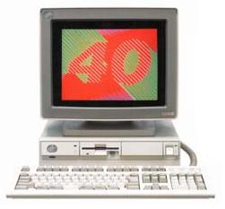
5541 was released after 5550-S/T/V and it looks like PS/2 Mod. 53.
( I do not know the inside layout of Mod.53 ).
This machine can not take any Display Adapters other than Display Adapter
B-II for it's video sub-system.
Reference
Ref. Ver. 1.00 to Ver.1.36 are based on JDOS.
Ref.Ver higher than 1.4x are based on DOS/V.
Ver. 1.50 covers most of of all 386 models such as 5550-S/T/V,
5570-T/V, 5540-T, 5530-T.
Video
Display Adapter B-2 was used for this
model. VGA chip is not provided on the planar. 2003.02.27
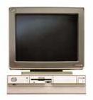
Noticed that a Display adapter seen in the
piture is not a B-II but more looks like V ( AVEC ).
Don't know if it is a B ( BVEC ) or any other kind of AVEC family.
( PS/55Z 5510-T which is very simmular to 5540 can be configured
with XGA /A. )
Memory
Capacity P/N
2MB
23F3270, 59F9046, 79F2566
4MB
79F2536,
8MB
79F2500
Hard Disk
interface
Same as 8570, ESDI ( roughly speaking ).
Planar
(
386DX-20MHz )
5540-T planar
Outline was drawen and donated by Mr. Tahara
( a member off
FIBMJ # 4 ) |
Y1
14.31818
Y2 24.000
Y3 40.000
U8 NS16550AV
NS16550
U9 90X9298 8042
U11 35F3489 ADDR G/A
U12 65F0082 EPP-3
U17 33F5838 I/O GA
U22 35F3489 DATA G/A
U25 33F5946 CPU G/A
U26 i80386 80386 ( DX, so
called )
U27 90X8134
U29 79F1016 MEM G/A
U32 FPU???? 80387
U34 N828077AA ( FDD controller
)
U37 65F0155 ( BIOS EPROM
)
Connectors
J? Serial
J? Parallel
J? K/B
J? Mouse
J8 MCA BUS Riser with
an ESDI connector
J9 Memory Riser Slot
J10 FDD connector 34PIN
J14 SIMM Slot 72pin
J13 Power ? 8PIN (
or SP ? )
J16 Power ? 7PIN
J7 Main Power Connector
10PIN |
 |
<-- Rear view |
One SIMM slot J14 is placed on the planar and additional
2slots are provided through SIMM riser card which goes to
connector J9.
A BUS riser for J8 connector has MCA card slots on the
left
side and an ESDI HDD DB 2 connector is on the right side.
I/O connectors are placed as outline shows ( Cable
connectors are plugged in vertically ) |
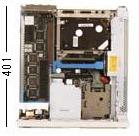 |
<-- Inner View
|
 |
PS/55 Index Page
|