 General SCSI-cabling rules - you NEVER should ...
 General SCSI-cabling rules - you NEVER should ...


 SCSI Bus Termination
Failure to properly terminate the SCSI bus will result in poor (wrong) signal quality and
noise on the bus. Errors caused by this condition may be intermittent, and difficult to diagnose.
Improper SCSI bus termination also causes operating system load problems and IML failures.

Most common SCSI Standards - Specifications
NOTE: Fast-20 Wide SCSI is also reffered to as UltraSCSI single ended.
The single ended refers to the length of the SCSI cable w/o using differential technology and w/o the
use of a SCSI repeater.
With an SCAM (SCSI Configured AutoMagically) Adapter installed, the adapter
use ID #6 during BOOT. All to an SCAM-adapter connected devices should support SCAM - otherwise conflicts.
Mixing Wide and Narrow External SCSI Devices
Please see the LEGAL - Trademark notice.
Mode
Bandwith
Frequ.
Max Data
Transfer
RateMax Cable
Length
Single-
-Ended
SCSI-I
8-bit
5 MHz
5 MBps
6 meters
SCSI-II
8-bit
5 MHz
5 MBps
6 meters
Fast SCSI
8-bit
10 MHz
10 MBps
3 meters
Wide SCSI
16-bit
5 MHz
10 MBps
6 meters
Fast/Wide SCSI
16-bit
10 MHz
20 MBps
3 meters
32-bit SCSI
32-bit
5 MHz
20 MBps
6 meters
32-bit Fast SCSI
32-bit
10 MHz
40 MBps
3 meters
Fast-20 SCSI
8-bit
20 MHz
20 MBps
1.5 m
Fast-20 Wide SCSI
(UltraSCSI)16-bit
20 MHz
40 MBps
1.5 m
The SCSI bus is a high speed bus that operates at speeds up to 5 megabits per second.
The bus must be terminated properly at both ends with resistor networks to minimize
signal reflections on the bus and to ensure proper voltage levels.
The following -PASSIVE- SCSI termination schemes may be encountered in the field:
(Only valid for passive SCSI-2 HD's - NOT valid for ULTRA, RAID and differential SCSI devices! )
The following rules are a guide for proper -PASSIVE- SCSI termination:
A useful publication for systems using SCSI devices is:
International Technical Support Centers, SCSI Arrchitecture and Implementation, GG24-3507-00
The following technical letter was found on INTERNET (Adaptec)
SCSI Terms and Definitions
There are 2 handshaking modes on the SCSI bus, used for transferring data: ASYNCHRONOUS and
SYNCHRONOUS. Asynchronous is a classic Req/Ack handshake. SYNCHRONOUS is 'sort of'
Req/Ack, only it allows you to issue multiple Req's before receiving Ack's. What this means in
practice is that SYNCHRONOUS transfers are approx 3 times faster than ASYNCHRONOUS.
SCSI-1 allowed asynchronous transfers at up to 1.5 Mbytes/Sec and synchronous transfers at up to
5.0 Mbytes/Sec.
SCSI-2 had some of the timing margins 'shaved' in order that faster handshaking could occur. The
result is that asynchronous transfers can run at up to 3.0 bytes/Sec and synchronous transfers at up
to 10.0 Mbytes/Sec. The term 'FAST' is generally applied to a SCSI device which can do
synchronous transfers at speeds in excess of 5.0 Mbytes/Sec. This term can only be applied to
SCS1-2 devices since SCSI-1 didn't have the timing margins that allow for FAST transfers.
Differential SCSI
For each signal that needs to be sent across the bus, there exists a pair of wires to carry it. The first
in this pair carries the same type of signal the single-ended SCSI carries. The second in this pair,
however, carries its logical inversion. The receiver takes the difference of the pair (thus the name
differential), which makes it less susceptible to noise and allows for greater cable length.

Single-ended SCSI (normal SCSI)
For each signal that need to be sent across the bus, there exist a wire to carry it.
Wide SCSI
SCSI may now transfer data at bus widths of 16 and 32 bits. Commands, status, messages and
arbitration are still 8 bits, and the B-Cable has 68 pins for data bits. Cabling was a confusing issue in
the closing days of SCSI-2, because the first project of SCS1-3 was the definition of a 16 bit wide
P-Cable which supported 16-bit arbitration as well as 16-bit data transfers. Although SCSI-2 does not
contain a definition of the P-Cable, it is quite possible that within the year, the P-Cable will be most
popular non-SCSI-2 feature on SCSI-2 products.
Fast SCSI
A 10 MHz transfer rate for SCSI came out of a joint effort with the IPI (Intelligent Peripheral Interface
commitee in ASC X3T9.3. Fast SCSI achieves 10 Megabytes/second on the A-Cable and with wider
data paths of 16 and 32 bits can rise to 20 Megabytes/second and even 40 Megabytes/second.
However, by the time the market starts demanding 40 Megabytes/second it is likely that the effort to
serialize the physical interface for SCSI-3 will attract high-performance SCSI users to the Fiber
Channel.
A word of caution. At this time the fast parameters cannot be met by the Single Ended electrical
class, and is only suitable for Differential. One of the goals in SCSI-3 is to identify the improvements
needed to achieve 10 MHz operation with Single Ended components.
SCSI Termination (PASSIVE-termination)
The Single Ended electrical class depends on very tight termination tolerances, but the passive 132
ohm termination defined in 1986 is mismatched with the cable impedance (typically below 100 ohms)
Allthough not a problem at low speeds when only a few devices are connected, reflections can cause
errors when transfer rates increase and/or more devices are added. In SCS1-2, an active terminator
has been defined which lowers termination to 110 ohms and is a major boost to system integrity.
Command Queuing
In SCSI-1, initiators were limited to one command per LUN e.g. a disk drive. Now up to 256
commands can be outstanding to one LUN. The target is allowed to re-sequence the order of
command execution to optimize seek motions. Queued commands require Tag messages which
follow the Identify.
Is SYNCHRONOUS faster than ASYNCHRONOUS ?
Asynchronous is faster on short cables, while synchronous is faster on long cables. The reason has
to do with the propagation delay of the cable; the turn around time of the silicon; and the interlocked
nature of the asynchronous handshake.
First REQ goes true (driven by Target) , then ACK is permitted to go true (driven by Initiator) , then REQ is permitted to go false, then ACK is permitted to go false.
Thus we have four 'edges' propagating down the cable plus 4 turn-around delays. Asynchronous
transfer requires 55 ns setup and no hold time (paragraph in 5.1.5.1 in SCS1-1 or SCS1-2) which gives
an upper speed limit around 18 MB/s. A detailed analysis shows that the setup time subtracts out.
This is mostly because we are running at one-third the max rate, but also because setup for the next
byte can begin anytime after ACK is received true or REQ is received false, depending on who is
receiving. You can either take my word for it or draw the waveforms yourself. Thus, the asynchronous
transfer reduces to:
4 * 1.7 * 1) + (4 * 40 ns) = 167 ns = 6 MB/s (1 foot cable)
(4 * 5.25 * 6) + (4 * 40 ns) = 286 ns = 3.5 MB/s (6 meter cable)
(4 * 5.25 * 25) + (4 * 40 ns) = 685 ns = 1.5 MB/s (25 meter cable)
Note: Cables longer than 6 meters require external differential transceivers which add delay and
degrade the performance even more than indicated here.
Our simulations say that under very best conditions (fast silicon, low temperature, high voltage, zero
length cable) we can expect more than 8 MB/s asynchronously. In the lab, I routinely measure 5 MB/s
on 8 foot cables. So, if you were writing the data manual for this, how would YOU spec it?
The framers of the SCSI spec threw in synchronous mode to boost the performance on long cables.
In synchronous mode, the sending device is permitted to send the next byte without receiving
acknowledgment that the receiver actually received the last byte. Kind of a ship and pray method. The
acknowledgment is required to come back sometime, but we just don't have to wait for it (handwave
the offset stuff and the ending boundary conditions). In this mode any external transceivers add a
time shift, but not a delay. So if you negotiate for 5 MB/s, you get 5 MB/s regardless how long the
cable is and regardless whether you are single-ended or differential. But you can't go faster than 5.5
MB/s, except in SCSI-2.
Synchronous mode does have a hold time (unlike asynch) but again, setup and hold times subtract
out. In SCSI-1 synchronous mode, the speed limit comes from the combined ASSERTION PERIOD +
NEGATION PERIOD which is 90ns + 90ns = 180 ns = 5.5 MB/s. Our 53C90 family doesn't quite hit
the max, but we do guarantee 5.0 MB/s. In SCSI-2, anything above 5.0 MB/s is considered to be
FAST. Here the maximum transfer rate is explicitly limited to 100 ns or 10MB/s; you don't have to
read between the lines to deduce it.
Interesting tid-bit: given a SCSI-2 FAST period of 100 ns and a cable delay of 131 ns on a 25 meter
cable, you can actually stack 1.31 bytes in the 8-bit cable. In FAST and WIDE SCSI you can stack
5.24 bytes in this copper FIFO.
Active / Passive - Terminator sample
An active terminator actually has one or more voltage regulators to produce the termination voltage,
rather than using resistor voltage dividers.
This is a PASSIVE terminator: (one signal-line example)
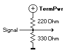
Notice that the termination voltage varies with the voltage on the TERMPWR line. One voltage
divider (two resistors) is used for each SCSI signal.
An ACTIVE terminator looks more like this:
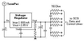
You MUST use ACTIVE-termination if an ULTRA or RAID SCSI adapter is installed !
(It's not wrong to use active termination if bus-speed is <= 10MByte/sec, but if bus-speed > 10MByte/sec, you must use
active termination).
Assuming that the TERMPWR voltage doesn't drop below the desired termination voltage (plus the
regulator's minimum drop), the SCSI signals will always be terminated to the correct voltage level.
Server 325/330 recommendations for ULTRA-SCSI (SCSI-3) support are:
NOTE: The following are guidelines, and many setup which break this rules will still work.
Setups which stick to the below rules will have the best chance of working.
Mixing SCSI Types.
The prime concern when intermixing devices operating with differen SCSI configurations is the
data bus width. The 50-pin connector used for external SCSI-1 and SCSI-2 FAST devices will not
support greater than 8 bits.
So to use WIDE devices, they must be placed physically before the 8-bit devices. Also highlighted
is that the bus lines that are cut off, must be terminated as usual.
68-pin SCSI-2 Wide or 50-pin SCSI-2 Fast or
Fast & Wide device SCSI-1 device
+----+ +----+
----| |------------------------| |------
| | Control Bus | |
----| |------------------------| |------
from previous | | | | to next SCSI-1
--------> | | | | -------> or
Wide device | | | | SCSI-2 FAST (only)
or ----| |------------------------| |------ device
Controller | | Data (0-7) | |
----| |------------------------| |------
----| |-----------------++ | |
| | Data (8-15/32) ||T | |
----| |-----------------++ | |
+----+ +----+
Wide SCSI Cable Wide (68-pin) to SCSI-1 (50-pin)
(68-pin) SCSI-1 (50-pin) Cable
with termination (T)
For internal use the bus cable will be the same for its whole length, therefore,
all signal lines can be terminated at the end. In such cases the data bus width
reduction can be performed without termination.
Term-Power Rules
When SCSI-I Adapter/Devices are used, the Adapter only should
supply termination power.
When SCSI-II Adapter/Devices are used each Adapter and/or Device can
supply termination power. As a general rule, (for SCSI-II, F/W, Ultra..)
only the Adapter should supply termination power. If the SCSI cable is
very long (>1.2m), Term-Power also should/can be supplied from the last device (in chain) on this cable, but
all other devices in such a chain, should not have Term-Power enabled.
The following statements, where found on Internet Adaptec http://www.adaptec.com/support
Conneting 8-bit and 16-bit Devices to an Adaptec Wide Host Adapter
Adaptec wide host adapters available: 2740W, 2742W, 2744W, 2940W, 2940UW Mac, 2944W,
2940UW, 3940W, 3940UW, 3940UW Mac, 3940 UWD and 3944UWD.
Definition - Narrow / Wide SCSI-Devices
The narrow signal cable carries the Low Data Bytes and the
Control signals
The wide signal cable carries the Low Data Bytes the
High Data Bytes and the Control signals
Low data byte = data bit's 0 to 7 - High data byte = bit's 8 to 15.
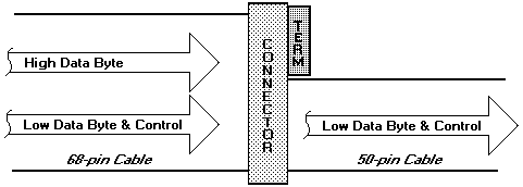
 68-pin to 50-pin external converters are available from various manufacturers. Only converters that
actively terminate the High Data Bytes should be used.
Internal Converter Kit usage
In the below example, an internal converter converts a 68-pin wide ribbon cable to a 50-pin connector. The converter is used only to
convert the 68-pin to a 50-pin connector (needed for narrow device) but has no termination for the high data byte, because a termination is only
once at the end of the cable allowed/needed.
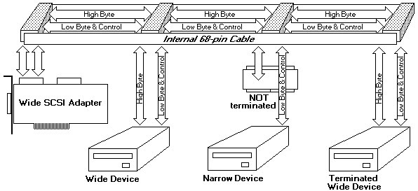
External Devices - Connection Examples.
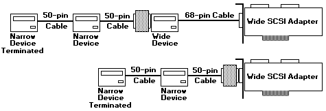
Internal Devices - Connection Examples.

There exist several Converters / Convert-Terminators for Wide SCSI to Narrow conversion.
Back to ![]()
Feel free - send a  for any BUG on this page found - Thank you.