IEEE 1284-1994 Electrical Interface - Cable
IEEE 1284 Electrical Interface - Cable
The original parallel port did not have a defined electrical specification that
identified the driver, receiver, termination and capacitance requirements in order to
guarantee any compatibility between devices. Host adapters and peripherals were built
with any number of pull-up values on the control lines, open collector or totem pole
drivers for the data and control lines, and most offensive of all, up to 10,000pF capacitors
on the data and strobe lines. This type of design variation makes it impossible to create a
new interface protocol without explicitly defining the required electrical parameters with
which to guarantee operation.
The 1284 standard defines two levels of interface compatibility, Level I and Level
II. The Level I interface is defined for products that are not going to operate at the high
speed advanced modes, but need to take advantage of the reverse channel capabilities of
the standard. The Level II interface is for devices that will operate in the advanced modes,
with long cables, and at the higher data rates. This discussion will deal primarily with
Level II interfaces. Please refer to the standard for the full requirements for either a Level
I or Level II interface.
The requirements for the Level II drivers and receivers are defined at the connector
interface. The driver requirements are:
- The open circuit high-level output voltage shall not exceed +5.5V.
- The open circuit low-level output voltage shall be no less than -0.5V.
- The DC steady state, high-level output voltage shall be at least +2.4V at a source current of 14mA.
- The DC steady state, low-level output voltage shall not exceed +0.4V at a sink current of 14mA.
- The driver output impedance (Ro), measured at the connector, shall be 50 +/- 5 ohms at 1/2 the actual
driver Voh minus Vol voltage.
- The driver slew rate shall be 0.05-0.40 V/nS
Like the driver requirements, the receiver requirements are defined at the
connector interface. The receiver requirements are:
- The receiver shall withstand peak input voltage transients between -2.0V and +7.0V without damage or improper operation.
- The receiver high-level input threshold shall not exceed 2.0V
- The receiver low-level input threshold shall be at least 0.8V.
- The receiver shall provide at least 0.2V input hysteresis, but not more than 1.2V.
- The receiver high-level sink current shall not exceed 20uA at +2.0V.
- The receiver low-level input source current shall not exceed 20uA at +0.8V.
- Circuit and stray capacitance shall not exceed 50pF.
Figure 1 shows the recommend termination for a driver/receiver pair.
Ro represents the output impedance at the connector. It is intended that this impedance match
the cable impedance so as to minimize the noise caused by mismatched impedances.
Depending upon the type of driver used, a series resistor, Rs may be required to obtain the
correct impedance.
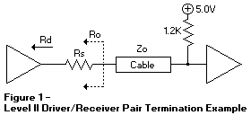
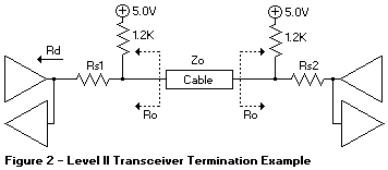
Figure 2 shows the recommended termination for a Level II transceiver pair, such
as the data lines.
There are products being introduced by some companies that provide
integrated solutions for a 1284 Level II interface.
These include active drivers and receivers as well as resister sip networks.
NOTE: When ECP was first introduced, Microsoft made a recommendation
for an electrical and termination requirement that was not consistent with the 1284 specification.
This included an AC terminator for each of the lines.
This suggestion has been retracted and the current recommendation is to use the interface defined
in the IEEE 1284 specification.
IEEE 1284 Cables Assemblies
In order to guarantee high performance operation, 10M cable lengths, and
interoperability among various platforms and peripherals, the 1284 standard defines the
characteristics for the cable assemblies.
Contrary to popular belief, there is no such thing as a 'standard' parallel printer
cable. This typically refers to a cable assembly with a DB25 male on one end and a 36
pin Champ plug connector on the other end. Internally, the cables may have from 18 to 25
conductors, with 1 to 8 ground wires, they may have foil shielding and/or braid, and
possibly a drain wire. With this type of assembly there is no way to control the cable
impedance, crosstalk, capacitance and performance. This type of assembly is fine for
operation at 10K bytes per second at 6 ft., but will not work reliably at 2M byte per
second at 30 ft. cable lengths.
Some of the parameters for a compliant 1284 cable assembly include:
- All signals are twisted pair with a signal and ground return
- Each signal and ground return has a characteristic unbalanced impedance of 62 +/- 6 ohms over the frequency band of 4 to 16 MHz
- The wire-to-wire crosstalk is to be no greater than 10%
- The cable will have a minimum of 85% optical braid coverage over foil.
- The cable shield shall be connected to the connector backshell using a 360 degree concentric method.
A pigtail connection is not acceptable.
- Compliant cable assemblies shall be marked with: 'IEEE Std 1284-1994 Compliant'
Standard cable lengths are available in 10 ft., 20 ft. and 30 ft. from some manufacturers.
Since this cable has such good performance there is no need to be limited to a 6 ft. cable
assembly.
Back to 
Please see the LEGAL - Trademark notice.
Feel free - send a  for any BUG on this page found - Thank you.