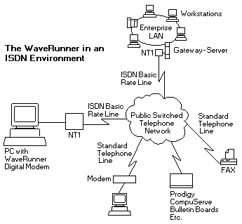
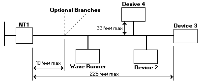
 In this chapter you will only see the WaveRunner techn. highlights. For a complete HW/SW install.-instruction,
it's a must, to order the above referenced manual. (more than 150 pages !).
 In this chapter you will only see the WaveRunner techn. highlights. For a complete HW/SW install.-instruction,
it's a must, to order the above referenced manual. (more than 150 pages !).
FRU P/N OPT P/N
-----------------------|---------|----------
WaveRunner ISA adapter | 73G1392 | 73G1393 U.S. only
| |
----- EMEA ------------|---------|----------
WaveRunner ISA adapter | 13H5520 | 13H5391 Not for Germany/France/Swiss
WaveRunner MC adapter | 13H5540 | 13H5411 Not for Germany/France/Swiss
Introduction to the WaveRunner Digital Modem
The IBM WaveRunner Digital modem is an adapter that provides a digital connection
to a personal computer system for communications over an intgrated services digital network (ISDN).
It communicates with most ISDN devices at 64Kbps and some proprietary configurations at 128Kbps, while
maintaining the ability to communicate through an ISDN to analog modems and facsimile (FAX) machines connected to an
existing telephone network.

The Waverunner is the only digital modem that provides these capabilities on a single adapter.
It's patented technology lets you take full advantage of today's emerging, high-speed digital communications networks
without abandoning existing technology.
ISDN is a network architecture that uses digital technology to support integrated voice, data, and image applications
through standard interfaces over regular telephone lines served by digital switches. This feature enables customers to have a mix of
different devices (ISDN and analog) in their establishment or enterprise and still maintain communications between all these devices.
Summarized features of the WaveRunner

Connecting the WaveRunner to the NT1
Installation Prerequesites
To install either WaveRunner adapter, you need:
Testing the WaveRunner Adapter for Micro Channel
Before running the diagnostics, make sure that the adapter is correctly connected to the ISDN line
Setting the Switches for the WaveRunner adapter for ISA
REVISION A only
Switch Block 1 (REV A - S-1)
1 2 3 4 5 6 7 8
| | | | | | | |
| | | | | +------------ Not used
| | | | |
| | | | +------- DMA Re-questet Timer Value
| | | | ON = 4 usec
| | | | OFF = 1 usec (D)
| | | |
| | | +------------ COMM Port Disable
| | | ON = Disabled
| | | OFF = Enabled (D)
| | |
| | +----------------- COMM Port Select
| | ON = COM1 (03F8-03FF)
I/O Port Address OFF = COM2 (02F8-02FF) (D)
ON ON = Invalid
ON OFF = 4E30-4E3F
OFF ON = 8E30-8E3F
OFF OFF = CE30-CE3F (D)
Switch Block 2 (REV A - S-2)
1 2
| |
DMA Channel Select
| |
ON ON = DMA 0
ON OFF = DMA 6
OFF ON = DMA 0
OFF OFF = DMA 7 (D)
Switch Block 3 (REV A - S-3)
1 2 3 4 5
| | | | |
| | | COMM Port IRQ
| | | ON ON = IRQ 5
| | | ON OFF = IRQ 3
| | | OFF ON = IRQ 4
| | | OFF OFF = IRQ 3 (D)
| | |
| | +-- System IRQ
| | ON = SYS IRQ 11
| | OFF = SYS IRQ 15 (D)
| |
| +------- DMA Byte/Word Select
| ON = 8/16 Bit
| OFF = 16 Bit only (D)
|
+------------ SIO Channel Ready Gated Timing Select
ON = Mod 30-286 Mode
OFF = Normal Mode (D)
Setting the Switches for the WaveRunner adapter for ISA
REVISION B only
Switch Block 1 (REV B - S-1)
1 2 3 4 5 6 7 8
| | | | | | | |
| | | | | | +------- Not used
| | | | | |
| | | | | +-- DMA Requested Timer Value
| | | | | ON = 4 usec
| | | | | OFF = 1 usec (D)
| | | | |
| | | | +------- COMM Port Disable
| | | | ON = Disabled
| | | | OFF = Enabled (D)
| | COMM Port Select
| | ON ON = COM2 (02F8-02FF)
| | ON OFF = COM1 (03F8-03FF)
| | OFF ON = COM4 (02E8-02EF)
| | OFF OFF = COM3 (03E8-03EF) (D)
| |
I/O Port Address
ON ON = 0120-012F
ON OFF = 0130-013F
OFF ON = CE20-CE2F
OFF OFF = CE30-CE3F (D)
Switch Block 2 (REV B - S-2)
1 2
| |
DMA Channel Select
| |
ON ON = DMA 0
ON OFF = DMA 6
OFF ON = DMA 0
OFF OFF = DMA 7 (D)
Switch Block 3 (REV B - S-3)
1 2 3 4 5
| | | | |
| | | COMM Port IRQ
| | | ON ON = IRQ 3
| | | ON OFF = IRQ 5
| | | OFF ON = IRQ 4
| | | OFF OFF = IRQ 5 (D)
| | |
| | +-- System IRQ
| | ON = SYS IRQ 11
| | OFF = SYS IRQ 15 (D)
| |
| +------- DMA Byte/Word Select
| ON = 8/16 Bit
| OFF = 16 Bit only (D)
|
+------------ SIO Channel Ready Gated Timing Select
ON = DMA Gated
OFF = Normal Mode (D)
Micro Channel Configuration Parameters-Description and Options
Please see the LEGAL - Trademark notice.
Parameter
Description
Available Options
COMM Port
This parameter assigns
the communication
(COMM) port a value from
COM1 to COM8, or
disables the COMM port.
Each COMM port value
assigned is accompanied
by an Interrupt Request
(IRQ) value. This value
establishes the priority
with which the adapter
can interrupt the
computer. The lowest
value is given the highest
priority.COM1, IRQ 4
COM2, IRQ 3
COM3, IRQ 3
COM4, IRQ 3
COM4, IRQ 4
COM5, IRQ 3
COM5, IRQ 4
COM6, IRQ 3
COM6, IRQ 4
COM7, IRQ 3
COM7, IRQ 4
COM8, IRQ 3
COM8, IRQ 4
DISABLED
I/O Address
SelectionThis parameter selects the
I/O address range that is
used by the adapter.0400-041F 04F8-04FF
0800-081F 08F8-08FF
0C00-0C1F 0CF8-0CFF
1000-101F 10F8-10FF
1400-141F 14F8-14FF
1800-181F 18F8-18FF
1C00-1C1F 1CF8-1CFF
2000-201F 20F8-20FF
2400-241F 24F8-24FF
2800-281F 28F8-28FF
2C00-2C1F 2CF8-2CFF
3000-301F 30F8-30FF
3400-341F 34F8-34FF
3800-381F 38F8-38FF
3C00-3C1F 3CF8-3CFF
4000-401F 40F8-40FF
4400-441F 44F8-44FF
4800-481F 48F8-48FF
4C00-4C1F 4CF8-4CFF
System
Interrupt
SelectionThis parameter sets the
System Interrupt Level.
The value for this
parameter establishes the
priority by which the
WaveRunner can interrupt
the computer.Interrupt Level 15
Interrupt Level 11
Arbitration
LevelThis parameter selects the
arbitration level at which
the WaveRunner will
operate.
Under normal conditions,
you should accept the
default value for this
parameter.Level 1
Level 3
Level 5
Level 6
Level 7
Level 8
Level 9
Level A
Level B
Level C
Level D
Level E
Fairness
Enable/DisableThis parameter
establishes wheter or not
the adapter will share the
bus with other devices or
retain control of the bus
as needed. Under normal
conditions, Fairness
Disable is preferred.Fairness Disable
Fairness Enable
Back to ![]()
Feel free - send a  for any BUG on this page found - Thank you.