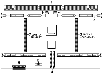
Processor-controller board component locations
A simplified layout of the processor controller board is shown in the following illustration.
Processor-controller board jumpers
(Below) Table 14 describes the jumper on the processor controller board.
The highlighted number in the table corresponds to the highlighted number on the illustration in
(above) 'Processor-controller board component locations'.
Notes:
MHz denotes internal clock speed of the processor only; other factors also affect application performance.
 -Attention- Be sure that the processor bus-to-core ratio
jumper is properly set. If the processor bus-to-core ratio does not match the processor speed in the server,
the server might operate with a degraded performance or not at all.
-Attention- Be sure that the processor bus-to-core ratio
jumper is properly set. If the processor bus-to-core ratio does not match the processor speed in the server,
the server might operate with a degraded performance or not at all.
Processors listed in Table 14 are not necessarily available or planned for your model.
If a processor becomes available for your model, use these switch settings.
Table 14. Processor-controller board jumper
Please see the LEGAL - Trademark notice.
Jumper name
Description
-3-
Processor-core-frequency-selection
The default core/bus fraction is 5.5 (550/100 MHz).
Pins 9/10, 11/12, and 13/14 are closed.
Pins 15/16 are open.
For the core/bus fraction 6.0 (600/100 MHz), pins 9/10, 11/12, and 13/14 are open.
Pins 15/16 are closed.
For the core/bus fraction 6.5 (650/100 MHz), pins 9/10 and 15/16 are closed.
Pins 11/12 and 13/14 are open.
For the core/bus fraction 7.0 (700/100 MHz), pins 9/10 and 11/12 are open.
Pins 13/14 and 15/16 are closed.
For the core/bus fraction 7.5 (750/100 MHz), pins 9/10, 13/14, and 15/16 are closed.
Pins 11/12 are open.
Note:
Open = No jumper is present.
Closed = A jumper is present.
Back to ![]()
Feel free - send a  for any BUG on this page found - Thank you.