Jumper settings - (NF 8500R - Type 8681)
Jumper settings
Jumpers located on the I/O function card and processor controller board help you to customize
the way the server operates.
The processor controller board and I/O function card contain two-pin jumper blocks and three-pin jumper blocks,
respectively. In some cases, groups of jumpers might combine to define a function.
Before you begin:
Read 'Safety information'.
To change a jumper setting:
- Remove the server top cover or front bezel, depending on the location of the jumper
(see 'Preparing to install options').
- Locate the jumper whose setting you want to change:
- To change a two-pin jumper block, continue with 'Two-pin jumper blocks.'
- To change a three-pin jumper block, continue with 'Three-Pin jumper blocks'.
Two-pin jumper blocks: Two-pin jumper blocks are located on the processor controller board.
Covering both pins with a jumper defines one function of the jumper block.
To change the function of the jumper block, cover one pin only or remove the jumper entirely.
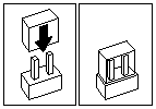
The following illustration identifies pins 1 and 2 on a two-pin jumper block.

To change the jumper setting on a two-pin jumper block:
- Lift the jumper straight off the block; then, do one of the following:
- Align the holes in the bottom of the jumper with the two pins on the pin block, and then slide the
jumper carefully onto these pins.

- Align one of the holes in the bottom of the jumper with one of the pins on the pin block, and
then slide the jumper carefully onto that pin only.

- Reinstall the server top cover or front access cover and connect the cables
(see 'Completing the installation').
Three-Pin jumper blocks:
Three-pin jumper blocks are located on the I/O function card.
With the three-pin jumper blocks, each jumper covers two of the three pins on a pin block.
You can position the jumper to fit over the center pin and either of the other two pins.
The following illustration identifies pins 1, 2, and 3 on the three-pin jumper blocks that are described in this chapter:

To change the jumper setting on a three-pin jumper block:
- Remove the I/O function card from the server:
- Refer to the following illustration while you perform the steps in this procedure.

- Disconnect all cables -1- from the I/O function card -2-.
Note carefully where each cable is connected before you remove it.
See 'I/O function card component locations' for the connector locations on the I/O function card.
- Remove the two screws -4- located on the metal connector plate inside the server.
- Remove the I/O function card retention bracket -3- on the right side of the card by pulling out
the fastener on the bracket.
- Carefully grasp the I/O function card by its top edge and pull the I/O function card out of the server.
- Place the I/O function card connector-side up on a flat, static-protective surface.
- Lift the jumper straight off the pin block.
- Align the holes in the bottom of the jumper with the center pin and the pin that was not covered previously.

- Slide the jumper fully onto these pins.
- Reinstall the I/O function card:
- Refer to the illustration in (above) step 1a while you perform the steps in this procedure.
- Carefully grasp the I/O function card by its top edge, and insert the tabs on the bottom edge of
the metal connector plate into the matching openings on the server back panel.
- Align the I/O function card with the guide on the opposite end of the adapter and the slot on the I/O board.
- Press the I/O function card firmly into the slot.
 -Attention- When you install the I/O function card in the server, be sure that it is completely
and correctly seated. Incomplete insertion might cause damage to server components.
- Reinstall the I/O function card retention bracket that you removed in (above) step 1d by
pressing in the fastener on the bracket.
- Insert the two screws that you removed in (above) step 1c.
- Connect the cables that you disconnected in (above) step 1b.
See 'I/O function card component locations' for the connector locations on the I/O function card.
- Reinstall the server top cover or front access cover and connect the cables
(see 'Completing the installation').
Back to 
Please see the LEGAL - Trademark notice.
Feel free - send a  for any BUG on this page found - Thank you.


 -Attention- When you install the I/O function card in the server, be sure that it is completely
and correctly seated. Incomplete insertion might cause damage to server components.
