Installing the Server in the Rack Enclosure - Netfinity 5600 - Type 8664
Installing the Server in the Rack Enclosure
This process is divided into two parts: preparing the rack and installing the server.
 -Important-
- Installing the server in a rack requires three people.
- To ensure cabinet stability, install the servers starting from the bottom of the rack enclosure.
- If you are installing different server models in the rack enclosure, install the heaviest models in the
lower part of the rack enclosure.
You will need a flat-blade screwdriver.
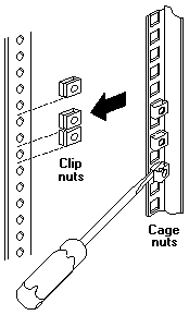
Note: In preparing the rack you will use either cage nuts or clip nuts, as appropriate for the style rack.
For brevity, this document uses the term cage nuts only.
Preparing the rack enclosure: Complete the following procedure to attach
the mounting hardware to the rack enclosure.
- Mark the positions of the slide brackets and the cable management arm on the
mounting rails of the rack enclosure.
- Position the template on the front mounting rail, aligning the holes.
- Mark the holes for the slide bracket cage nuts, using the dots supplied with the template.
If you require additional security for the server, also mark the holes for the chassis bracket cage nuts.
- Move the template to the rear mounting rails.
Mark the locations for the slide bracket cage nuts and the cable-management-arm mounting bracket.
Note: You must align the slide brackets correctly or the installation cannot be completed.
- Install the cage nuts in the marked positions as shown.
- Attach the slide rails to the rack.
- Insert the left slide rail -1 rear bracket pin into the hole between the two cage nuts for the slide
rail at the rear of the rack.
The two holes in the rear bracket line up with the cage nuts.
- Pull the slide rail front bracket to the front of the rack; insert the front bracket pin into the hole
above the cage nuts for the slide rail.
The two holes in the front bracket line up with the cage nuts.
- Do the same for the other slide rail.
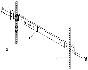
2 Left rear
3 Left front
1 Left slide rail
- From the outside of the rack enclosure, insert two M6 by 16-mm screws through each slide rail
bracket and cage nuts; then, finger-tighten the screws.
- Attach the cable-management arm to the left rear of the rack enclosure.
- Align the cable-management-arm mounting bracket with the cage nuts on the rear mounting rail.
- Insert two M6 by 16-mm screws to secure the mounting bracket to the rack.
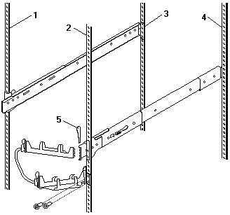
1 Right rear
2 Left rear
3 Right front
4 Left front
5 Hitch pin
- Attach the free end of the cable-management arm to the rear of the left slide rail, using a hitch pin -5-.
Installing the server: Complete the following procedure to install the server into the rack enclosure.
- Mount the server on the slide rails.
- Attach the large wheel-shaped knobs -1- to the sides of the server, near the rear of the server.
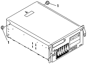
- Extend the slide rails fully from the rack until the slide rails lock.
- Rest the wheel-shaped knobs -1- on the slide rails at a point close to the rack.
- Lower the front of the server until the bottom notch in each chassis bracket fits into the top
notch in the slide rail end.
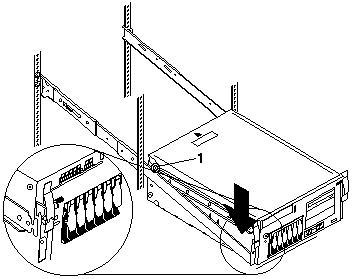
Slide the server backward or forward as necessary until the notches meet.
- Attach the rails to the sides of the server with M4 by 5-mm screws.
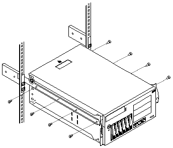
- Remove the wheel-shaped knobs from the server.
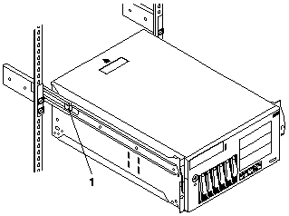
- Press the safety latches -1- on the slide rails and slide the server about halfway into the rack enclosure.
Note: When the server is fully extended, safety latches on the slide rails lock into place.
This prevents the server from being accidentally pulled out too far and dropped.
To release the safety latch, press in.
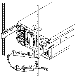
- Attach the cables to the server.
- Attach the monitor, keyboard, and power cables to the corresponding connectors on the server.
Refer to the rack enclosure documentation for instructions.
- Attach any other cables you removed before you converted the server to a rack model.
- Route all the cables through the cable-management arm, attaching the cables to the arm
with the hook and loop fastener strips provided.
Tie wraps are provided for additional cable management beyond the cable-management arm.
- Secure the server in the rack enclosure.
- Slide the server into the rack enclosure until the slide latches on the front chassis
brackets click into place.
- Using a screwdriver, tighten the screws that hold the rear of the slide rails to the rear of the rack.
- Release the server and pull the server forward about half-way.
Note: To release the server, release the left and right slide latches and pull the server forward.
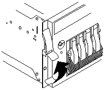
- Using a screwdriver, tighten the screws that hold the front of the slide rails to the front of the rack.
- Slide the server into the rack enclosure again until the slide latches on the front chassis
brackets click into place.
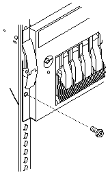
- (Optional) For additional security, such as when transporting the rack, fasten the server to the rack
enclosure by inserting a M6 by 16-mm screw through the chassis bracket, mounting rail, and cage nut on each side.
- Connect all server and device cables and connectors.
- Use the server configuration program to reconfigure the server.
Because of the new orientation of the server, you must change the server configuration so that the
Netfinity Manager program will show a graphic of a rack model for this server instead of showing a tower model.
- Press the power control button to turn on the server, and watch the display.
- When the messages Press F1 for Configuration/Setup and Press F2 for Diagnostics appear, Press F1.
- Select System Information; then select Product Data.
- Change the machine type and model from a tower model to a rack model.
1) Find the machine type and model in the Tower column in the following table.
2) Change it to the machine type and model shown in the Rack column.
| Tower |
Rack |
| 8664-11Y |
8664-1RY |
| 8664-21Y |
8664-2RY |
- Press Esc to return to the main configuration utility menu.
- Select Save Settings; then select Exit Setup.
- Insert the IBM Netfinity Hot-Plug SCSI Setup Utility diskette in
diskette drive a: and restart the system.
The utility on the diskette starts automatically and updates the drive order of the SCSI IDs for
reporting purposes.
A progress indicator displays during both stages of the utility (up to three minutes), followed by
a message that indicates successful or unsuccessful completion of the utility.
- If the utility did not complete successfully, restart the server to retry the utility.
If the utility repeatedly fails to complete successfully, contact the authorized service representative.
- If the utility completed successfully, remove the diskette, turn off the server, wait 30 seconds,
and restart the server.
- The tower-to-rack conversion is complete.
Back to 
Please see the LEGAL - Trademark notice.
Feel free - send a  for any BUG on this page found - Thank you.
 -Important-
 -Important-


 for any BUG on this page found - Thank you.