Installing the Conversion Kit on the Server - Netfinity 5600 - Type 8664
Installing the Conversion Kit on the Server
Before You Begin:
- Read through these instructions to familiarize yourself with the installation procedure.
- Read 'Safety information'.
Note: The illustrations in this publication might be slightly different from the hardware.

 -Caution- Use safe lifting practices when lifting the machine.
Complete the following procedure to install the conversion kit on the server.
- Prepare the server for conversion.
- Shut down the server operating system.
- Unlock the server door and open it by pulling on the door edge next to the lock.
- If desired, remove the server door.
1) Locate the flange on the top edge of the front door, near the hinge.
2) Press the flange downward while pulling the door forward or pressing out on the door;
then, lift the door off the hinge. Set the door aside.
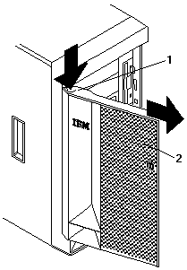
- Remove all removable media (diskettes, CDs, optical discs, or tapes) from the drives.
- Turn off the server and any attached devices, such as printers, monitors, and external drives.
- If you have a fax or modem attached to the server, disconnect the telephone line from the wall outlet and the server.
 -Caution- The power control button on the front of the
server does not turn off the electrical current supplied to the server.
The server also might have more than one power cord. To remove all electrical current from the server,
ensure that all power cords are disconnected from the power source.
- Disconnect all the power cords (cables) from electrical outlets.
- Disconnect all communication cables from external receptacles.
- Disconnect all remaining cables and power cords from the back of the server.
Remove the left-side cover.
- Locate the cover-release lever -1- on the front of the server and slide it to the right.
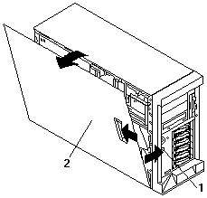
- Slide the left-side cover back about 25 mm (1 inch); then, lift the cover and remove it.
Obtain the new service label from the conversion kit; you might need to refer
to the service label during this procedure.
Remove the trim bezel.
- Locate the blue bezel-release lever -1- on the left side of the server in the top front corner.
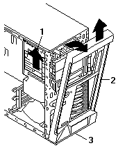
- Move the lever upward following the curve of the lever opening.
- Lift the bezel tabs out of the tab openings at the bottom front of the server and pull the bezel
away from the server front.
- Store the bezel in a safe place.
Remove the right-side cover.
- From the rear of the server, remove the screws holding the cover.
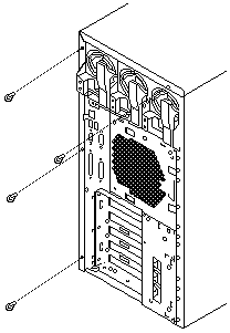
- Slide the cover toward the rear of the server about 25 mm (1 inch); then, lift the cover off the server.
Install the new bottom cover.
- Position the server open-side-down, as illustrated below.
- Select either server cover from the conversion kit to use as the bottom cover.
The remaining cover will be the top cover.
- Align the bottom cover with the frame of the server.
- Press the cover onto the server; then, slide the cover toward the front of the server, making sure
the tabs on the rear of the cover fit into the slots on the rear of the server.
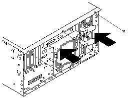
- Install two screws in the back of the cover.
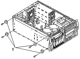
Position the server open-side-up on a flat, nonconductive surface.
Remove the feet -1- from the server by unscrewing them.
Remove the fan assemblies at the front of the server.
To remove a fan assembly, press the orange touchpoint Note 2 to release the fan assembly;
then, lift the fan assembly out.
Move the power switch panel -1- to its new location -2-.
Remove the hard disk drives.
Keep them in order so that you can return them to the same locations later.
Remove the power switch panel by pressing down and in on the arrow on the top blue tab.

Align the panel with its new location -2-, making sure that:
- The power control button is positioned above the reset button.
- The tab on the server inside front goes between the two posts on the power switch panel.
Place the squared end of the power switch panel bracket into the bottom opening, and press the
other end of the bracket toward the server front until the bracket clicks into place.
Move the operator LED panel -2- to its new location -1.

- Remove the operator LED panel bracket by pressing firmly on the bottom of the bracket
(on the arrow closer to the server) and pulling the bracket away from the server.
- Unplug the cable from the back of the operator LED panel.
- From inside the server, gently pull the cable toward the rear of the server until the cable is
free of the non-hot-swap bay area.
- Release the cable from the cable clip on the right side of the server, behind the non-hot-swap bays.
- Reroute the cable to the top left side of the server.
1) Run the cable along the top of the hard disk drive (HDD) backplane assembly
toward the left side of the server, tucking the cable under the two
protrusions at the rear of the HDD backplane assembly as you do so.
Note: The HDD backplane assembly is at the immediate rear of the fan platform.
2) Make sure to tuck the cable between the server left side and the HDD
backplane support; then, continue along the server left side to the
server left front corner.

- Reattach the cable to the operator LED panel.
Note: If you have difficulty connecting the cable, turn the cable connector over and try again;
the cable connector is keyed to connect only one way.
- Move the operator LED panel and bracket to the inside of the server, in its new location -1-.
- Place the notched end of the operator LED panel bracket into the opening -1-, aligning the LEDs
so that they show through the holes in the server front.

- Press the other end of the bracket through the other opening -2- until the bracket clicks into place.
Replace the front fan assemblies, ensuring that the cables clear the fans and do not block the flow of air.
Replace the hard disk drives you removed.
Reposition the CD-ROM drive and any other drives or filler panels in the non-hot-swap bays for rack operation.
- Remove the power and signal cables from the back of the drives in the non-hot-swap bays.
- Pull the drives and filler panels out of the server.
- Orient the drives so that they are top-side-up and horizontal.
- Insert the drives in the server.
- Insert filler panels into any unused non-hot-swap bays.
- Reconnect the power and signal cables to the back of the CD-ROM drive and other drives.
Install the new top cover.
- Install the service label on the inside surface of the top cover.
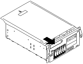
- Align the top cover with the top of the server, about 25 mm (1 inch) from the front of the server.
- Hold the top cover against the server and slide the cover toward the front of the server until the
cover clicks into place.
Note: Ensure that the tabs on the back of the cover fit into the slots on the back of the server.
Be sure the front edge of the cover is flat against the server.
Attach the chassis brackets.
- Insert the left bracket tab into the slot -2- in the left side of the server until the upper notch -1-
aligns with the side of the server.
Note: The left bracket is marked with an L.
- Push the bracket up until the holes in the bracket align with the holes in the side of the server.
- Insert two M3.5 by 7-mm screws through the left bracket into the holes on the left side of the
server; then, tighten the screws.

- Perform steps 16a through 16c using the right bracket and the right side of the server.
Install the new trim bezel from the conversion kit.
- Align the tabs on the back of the bezel with the tab openings on the front of the server.
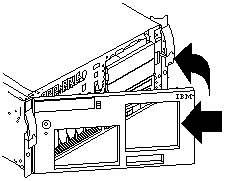
- Press the bezel into place until it clicks.
Continue the installation with 'Installing the server in the rack enclosure'.
Back to 
Please see the LEGAL - Trademark notice.
Feel free - send a  for any BUG on this page found - Thank you.


 -Caution- Use safe lifting practices when lifting the machine.
 -Caution- The power control button on the front of the
server does not turn off the electrical current supplied to the server.


 for any BUG on this page found - Thank you.