Installation Procedure for a 7337 Tape Library Model 306
Installation Procedure for a 7337 Tape Library Model 306
Use the tollowing procedure to install a 7337 Tape Library Model 306 in an EIA instrument rack.
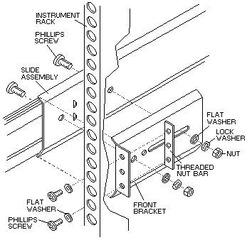
Before starting the installation, review the information in below Figure 52, which shows an exploded
view of the slide assembly and front mounting bracket relative to the EIA instrument rack.

Figure 52. Exploded View of EIA Rack-Mounting Components
 -CAUTION-
The weight of this part or unit is between 32 and 55 kilograms (70.5 and 121.2 pounds).
It takes three persons to safely lift this part or unit. (RFSTC2O5)
Attaching the Right Slide Assembly
- Place a slide assembly inside the instrument rack on the nght side (when viewed from the front).
Adjust the rear (long) bracket so the flanges on the front and rear brackets press against the inside of the instrument rack.
- Attach the front bracket to the instrument rack by inserting two 10-32 screws
through the front of the instrument rack, through the front bracket, and into a
threaded bar nut (see Figure 52).
Insert screws into only the top and bottom holes of the bracket and tighten them only finger tight (to allow for adjustment).
- Attach the rear bracket to the instrument rack by inserting three 10-32 screws
through the rear of the instrument rack, through the rear bracket, and into a
threaded bar nut. (The assembly is similar to that shown in Figure 52.)
Tighten the screws only finger tight to allow for adjustment.
- Adjust the front and rear mounting brackets so they~ are approximately 1/8-inch
(0.32 cm) from the edge of the instrument rack (see Figure 51).
Tighten the screws firmly.
- Tighten the screws that attach the slide assembly to the rear mounting bracket.
Attaching the Left Slide Assembly
- Repeat (below) steps 1, 2, and 3 to initially position and attach the left slide assembly to the instrument rack.
- Measure the distance between the slide assemblies at both the front and rear brackets.
The distance must be 17-1/2 in. (44.45 cm) (see Figure 50).
Adjust as necessary. Do not completely tighten the screws at this time.
Mounting the Tape Library
- Pull the left and right slide assembly rails out until the rails latch in the fully extended position.
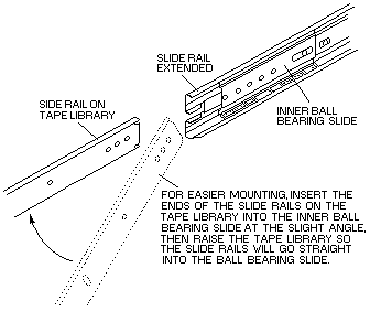
Ensure that the inner ball bearing slide is at the front of each slide (see Figure 53).
 -Attention- To prevent the rack from rolling, make sure that its castors are
blocked or locked before inserting the tape library.
- Lift the tape library and insert the rails mounted on the tape library chassis into the extended slide assembly rails.
Make sure that the tape library is straight relative to the slide assembly and that the tape library rails are in the guides at
the front of the slide assembly rails (see below Figure 53).
It may be necessary to first dip the front of the tape library then lift it up to
properly join the rails on the tape library with the slide assembly rails.

Figure 53. Mounting The Tape Library onto the Slide Assembly
- Slide the tape library into the instrument rack. Push the spring latch on the side of each rail to slide the tape library
completely into the instrument rack (see above Figure 53).
- Move the tape library in and out a few times to ensure that the slide rails are properly aligned and the tape library rolls smoothy on the slide rails.
- Tighten the 10-32 screws that secure the left slide assembly to the instrument rack.
- Open the tape library front door and install one 10-32 screw into each retainer tab next to the left and right front door hinge brackets.
- Close and lock the tape library front door.
Back to 
Please see the LEGAL - Trademark notice.
Feel free - send a  for any BUG on this page found - Thank you.


 -CAUTION-
 -Attention- To prevent the rack from rolling, make sure that its castors are
blocked or locked before inserting the tape library.

 for any BUG on this page found - Thank you.