Netfinity 7000 Rack Cluster Example
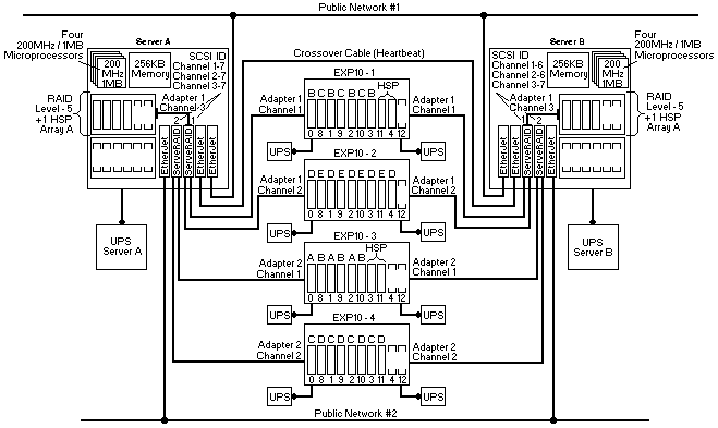
The network-crossover cable, sometimes referred to as the cluster's heartbeat, provides the dedicated,
point-to-point communication link between the servers. This cable connects two IBM 100/10 PCI EtherJet
Adapters (one in each server) and enables the servers to continuously monitor each other's functional status.
Notes:
Each server also contains two more EtherJet adapters. These adapters provide multiple connections to
external networks (in this example, Public Network 1 and Public Network 2).
Using the public-network connections and the dedicated heartbeat link together ensures that a single network-hardware failure will
not initiate a failover situation.
In both servers, the internal SCSI cable that connects to the backplane was moved from the Ultra SCSI
controller on the system board to the Channel 3 connector on ServeRAID Adapter 1.
Then, using Channel 3 of ServeRAID Adapter 1, three of the hard disk drives in each server were defined as RAID
level-5 logical drives (Array A). Because these nonshared drives store the operating system and
shared-disk clustering software needed during startup, these drives were defined first using the ServeRAID
configuration program.
In addition, this example shows multiple ServeRAID adapters installed in each server.
When you install multiple hard-disk controllers, RAID controllers, or ServeRAID adapters in the same server, you must install
the device that will manage the startup (boot) drives in a PCI slot that is scanned before subsequent hard-disk controllers or RAID adapters.
In the Netfinity 7000, the PCI slots are scanned in the following order: 1, 2, 3, 4, 5, 6.
To further increase availability, each server contains a hot-spare (HSP) drive for the internal nonshared array.
A hot-spare drive is a disk drive that is defined for automatic use in the event of a drive failure.
If a physical drive fails and it is part of a RAID level-1 or RAID level-5 logical drive, the ServeRAID adapter will automatically start
to rebuild the data on the hot-spare drive.
Note: ServeRAID adapters cannot share hot-spare drives. To maintain high availability and enable the
automatic-rebuild feature, you must define a hot-spare drive for each ServeRAID adapter.
The only difference between the hardware configuration of Server A and the hardware configuration of
Server B is the SCSI ID settings for the ServeRAID adapters.
Channels 1, 2, and 3 of both ServeRAID adapters in Server A are set to SCSI ID 7.
In Server B, Channels 1 and 2 of both ServeRAID adapters are set to SCSI ID 6, because they share the same SCSI buses as Channels 1 and 2 of the ServeRAID
adapters in Server A.
Channel 3 of ServeRAID Adapter 1 in Server B is set to SCSI ID 7, because it is not connected to any shared disks. Channel 3 of ServeRAID Adapter 2 in each server is available for use
as a quorum-arbitration link with the Microsoft Cluster Server software, or for future expansion with the Vinca clustering software.
In addition to the standard features of the Netfinity EXP10, the storage enclosures each contain eight or
nine hot-swap hard disk drives.
A SCSI cable (provided with each expansion enclosure) connects the SCSI Bus 1 OUT and SCSI Bus 2
IN connectors on the rear of the enclosures, forming one continuous SCSI bus in each enclosure.
Enclosure 1 contains nine 9.1 GB drives. Using auto-sensing cables, the SCSI Bus 1 IN connector is
attached to Channel 1 of ServeRAID Adapter 1 in Server A, and the SCSI Bus 2 OUT connector is
attached to Channel 1 of ServeRAID Adapter 1 in Server B.
Enclosure 2 also contains nine 9.1 GB drives. Using auto-sensing cables, the SCSI Bus 1 IN connector is
attached to Channel 2 of ServeRAID Adapter 1 in Server A, and the SCSI Bus 2 OUT connector is
attached to Channel 2 of ServeRAID Adapter 1 in Server B.
Enclosure 3 contains eight 9.1 GB drives. Using auto-sensing cables, the SCSI Bus 1 IN connector is
attached to Channel 1 of ServeRAID Adapter 2 in Server A, and the SCSI Bus 2 OUT connector is
attached to Channel 1 of ServeRAID Adapter 2 in Server B.
Enclosure 4 also contains eight 9.1 GB drives. Using auto-sensing cables, the SCSI Bus 1 IN connector
is attached to Channel 2 of ServeRAID Adapter 2 in Server A, and the SCSI Bus 2 OUT connector is
attached to Channel 2 of ServeRAID Adapter 2 in Server B.
Note: To help increase the availability of the shared disks and to enable the serviceability of a failing or
offline server, you must use Netfinity EXP10 Auto-Sensing Cables, IBM Part Number 03K9352, to connect clustered
servers to Netfinity EXP10 enclosures.
The EXP10 auto-sensing cables contain circuits that can automatically sense the functional status of the server.
When the circuitry in an auto-sensing cable detects that the server attached to it is failing or
offline, the cable circuitry automatically enables termination for that end of the SCSI bus.
This helps increase the availability of the shared disks and enables the serviceability of the failing or offline server.
To help maintain high availability, the 34 hard disk drives in the four EXP10 enclosures are defined as
eight, shared, RAID level-5 logical drives (notice the array designations of A, B, C, D, or E above each
drive). To further increase the availability of these drives, each ServeRAID adapter has its own hot-spare
drive (notice the HSP above four of the drives).
The SCSI ID assignments for the shared hot-swap drives are controlled by the backplanes inside the
Netfinity EXP10 enclosures.
The IDs alternate between low and high addresses, and might cause some confusion.
To avoid confusion with the SCSI IDs, consider placing a label with the SCSI IDs across the
front of the drive bays. In this example configuration, the SCSI ID assignments from left (bay 1) to right
(bay 10) are: 0 8 1 9 2 10 3 11 4 12.
Ideally, the servers and storage enclosures are connected to different electrical circuits, however, this is
rarely possible.
To help prevent the loss of data and to maintain the availability of the shared disks duringa power outage
or power fluctuation, always connect the servers and expansion enclosures to uninterruptible power supplies (UPS).
Please see the LEGAL - Trademark notice.
Feel free - send a  for any BUG on this page found - Thank you.