Installing the Processor Housing
Installing the Processor Housing
Complete this procedure to install the processor housing.
- If slot 6 contains an adapter, move the adapter to an empty slot.
If slot 5 contains a full-size adapter, move the adapter to an empty slot.
(Only half-size adapters will fit in slot 5.)
- Remove the slot 5 and 6 plastic guides opposite the bulkhead.
- If you have installed the SCSI Controller-to-Bulkhead
Cable option, remove the option and replace it with
the SCSI controller-to-bulkhead cable contained in this option:
- Detach the SCSI cable from the SCSI connector on the system board.

- Remove the screws from the external connector on the bulkhead opening.
- Connect one end of the SCSI cable contained in
this option to the SCSI connector on the system board.
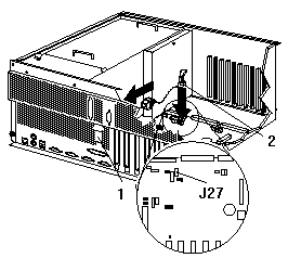
- Insert the SCSI cable external connector -1- into the knockout opening.
- Insert the two screws -2- that come with the
replacement SCSI cable into the external connector; tighten the screws.
- Optionally, install the RS-485 cable:
Note:
Only models with either 01K7234 or 28L1019 as
the system board assembly part number support
the RS-485 cable option.
The system board assembly part number is located near the battery
on the system board.
- Connect the RS-485 cable to the RS-485
connector (J27) -2- on the system board.
- Insert the external connector into the knockout opening -1-.
- Install the jumper extension cable on the Power on control jumper (J32):
- Note the position of the jumper on the pin block and remove the jumper.
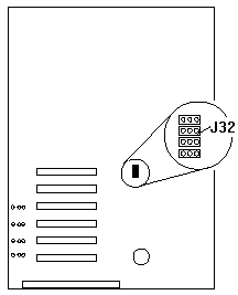
- Align the white cable with pin 1 and insert the connector over the pin block.
- If necessary, change the position of the jumper
on the jumper extension cable.
Note:
The default jumper position of J32 and the
jumper extension cable is a jumper on pins 1 and 2.
- Route the jumper extension cable along the system board and the shuttle side wall.
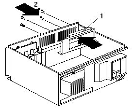
- Replace the processor housing guide:
- Remove the screws that secure the processor housing guide and remove the guide.
- Install the processor housing guide -1- that
comes with this option and secure with screws -2-.
- Replace the fan assembly and press on the fasteners to lock in place.
- Replace the processor housing top cover and press
on the fasteners to lock in place.
- Align the shuttle with the guides and slide the shuttle
partially into the server.
- Reconnect the cables to the shuttle that you disconnected in step 14 of
Removing the Shuttle and Processor Housing.
- Reconnect the power cables that you disconnected in step 3 of
Removing the Shuttle and Processor Housing.
- Grasp the handles on the processor housing top cover and lift the housing.
- Orient the processor housing with the cable
connectors toward the front of the server.
 -Attention-
When you install the processor housing in the server,
be sure that it is aligned correctly before seating in the shuttle.
-Attention-
When you install the processor housing in the server,
be sure that it is aligned correctly before seating in the shuttle.
Incorrect seating might cause damage to server components.
- Align the processor housing with the guides.
Carefully lower the processor housing into the shuttle until it is fully seated.
- Install and tighten the four blue thumbscrews.
- Install the half-card slot insulator between slot 5 and the processor housing.
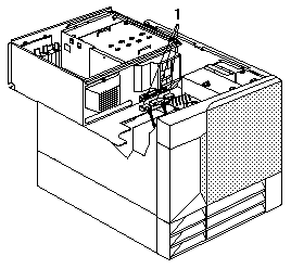
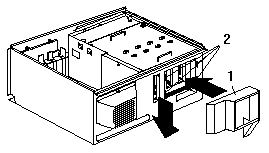
- Connect the power supply cables -1- to the processor housing.
- Secure the air diffuser -1- in the server by positioning
the air diffuser on the matching metal tabs 2 on the shuttle.
- Seat the shuttle in the server and tighten the four shuttle thumbscrews.
- Place the IBM Netfinity 5500 M20 system service
label on the inside of the top cover.
- Place one upgrade sticker near the machine type
serial number on the information label.
The upgrade sticker identifies the server as having this option installed.
Note:
The information label is located at the front of the
server behind the media-bay trim bezel.
- Place the other upgrade sticker on the front bezel,
above the machine type serial number.
- Place the Intel® microprocessor label on the front bezel.
- Reinstall the top cover.
- Check that all cables, adapters, and other
components are installed and seated correctly
and that you have not left loose tools or parts inside the server.
- Lower the cover with the rear edge of the cover
approximately 2.5 cm (1 in.) back from the rear edge of the server.
- Slide the cover forward.
- Tighten the two thumbscrews on the back edge of the cover.
- Go to Completing the Upgrade Installation.
Back to 
Please see the LEGAL - Trademark notice.
Feel free - send a  for any BUG on this page found - Thank you.